
matlab_controlled_robot
There are many variations in definitions of what exactly constitutes a robot. Consequently, it can be challenging to compare the number of robots across different countries. To provide a universally acceptable definition, the International Organization for Standardization (ISO) defines a robot in ISO 8373 as "an automatically controlled, reprogrammable, multipurpose manipulator programmable in three or more axes, which may be either fixed in place or mobile for use in industrial automation applications." There are numerous control system designs in MATLAB for controlling robots. Ascent has developed a fuzzy neuro-control system for a guided vehicle to operate in underground coal mines. MATLAB is the most recommended programming language for mathematical computations, making it convenient to design complex control systems for robots. However, to implement these control systems, the code must be converted to C language to be burned onto the microcontroller used in the robot. Often, the control system is too heavy in terms of memory consumption and processing power requirements for a microcontroller. Therefore, it is advisable to implement the control system in MATLAB on a PC and establish a duplex link between the robot and the PC. The objective of this project is to design a robot that can be controlled from the MATLAB environment. The robot will have two traction wheels, and by varying the angular velocity of the wheels, the direction and speed of the robot can be controlled. A microcontroller will manage the control of these wheels and will be designed to receive serial data through its UART port. A function will be developed in MATLAB that sends out four different codes to the robot through its serial port. The four code words are: stop, move forward, move right, and move left. A serial port is a physical interface for serial communication where information transfers one bit at a time. Historically, data transfer through serial ports connected computers to devices such as terminals and various peripherals. While interfaces like Ethernet, FireWire, and USB send data as a serial stream, "serial port" typically refers to hardware compliant with the RS-232 standard, meant to interface with modems or similar communication devices. Although the RS-232 standard originally specified a 25-pin D-type connector, many personal computer designers opted for a subset of the full standard, using less costly and more compact connectors, such as the DE-9 version used by the original IBM PC-AT. The presence of a nine-pin D-subminiature connector does not necessarily indicate the use of a serial port. Some miniaturized electronics, particularly graphing calculators and handheld amateur radio equipment, have serial ports using jack plug connectors, typically 2.5 or 3.5 mm, and employ a basic 3-wire interface. Various settings are required for serial connections used for asynchronous start-stop communication, including speed, number of data bits per character, parity, and the number of stop bits per character. In modern serial ports utilizing a UART integrated circuit, all settings are usually software-controlled; older hardware may require manual configuration through switches or jumpers on a circuit board. Serial ports use two-level (binary) signaling, so the data rate in bits per second equals the symbol rate in baud. The port speed and device speed must match, though some devices may automatically detect the speed of the serial port. The RS-232 standard is formally limited to 20,000 bits per second, but popular personal computers allow for much higher baud rates. Not all bit rates are compatible with all serial ports. Some special-purpose protocols, such as MIDI for musical instrument control, use serial data rates outside the standard series. The speed includes bits for framing (stop bits, parity, etc.), resulting in an effective data rate lower than the bit transmission rate. For instance, 8-N-1 encoding allows only 80% of the bits to be used for data (for every eight bits of data, two additional framing bits are sent). The number of data bits in each character can be 5 (for Baudot code), 6 (rarely used), 7 (for true ASCII), 8 (for any kind of data), or 9 (rarely used). Eight data bits are almost universally used in newer applications, while 5 or 7 bits are generally applicable only to older equipment like teleprinters. Most serial communications designs transmit the data bits within each byte as LSB (Least Significant Bit) first, also known as "little endian." Although "big endian" or MSB (Most Significant Bit) first serial communications are possible, they are rarely used. The order of bits is not usually configurable, but data can be byte-swapped prior to transmission. Parity is a method for detecting transmission errors. When parity is employed with a serial port, an extra data bit is sent with each data character, arranged so that the total number of 1 bits in each character, including the parity bit, is always odd or always even. If a byte is received with an incorrect number of 1 bits, it indicates corruption. If parity is correct, it does not guarantee the absence of errors but suggests an even number of errors may have occurred. Electromechanical teleprinters were designed to print a special character when received data contained a parity error, facilitating the detection of messages damaged by line noise. A single parity bit does not allow for error correction on each character, and communication protocols operating over serial data links will have higher-level mechanisms to ensure data validity and request retransmission of incorrect data. The parity bit in each character can be set to none (N), odd (O), even (E), mark (M), or space (S). None means no parity bit is sent, while mark parity indicates that the parity bit is always set to the mark signal condition (logical 1).
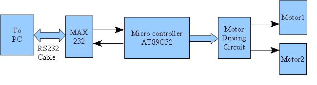
The design of the robot system incorporates several key components, including the microcontroller, MATLAB environment, and the serial communication interface. The microcontroller serves as the central processing unit that executes commands received from the MATLAB software. The control of the traction wheels is achieved by varying the pulse-width modulation (PWM) signals sent to the motor drivers, which in turn control the speed and direction of the motors.
The MATLAB environment is utilized for developing the control algorithms, which can include fuzzy logic, neural networks, or other advanced techniques for real-time decision-making. The established duplex link allows for continuous feedback from the robot, enabling the MATLAB system to adjust commands based on the robot's performance and environmental conditions.
The UART communication protocol is critical for the effective transmission of commands and data between the PC and the robot. The setup must be configured with appropriate baud rates, data bits, stop bits, and parity settings to ensure reliable communication. The serial communication must be robust enough to handle potential noise and interference, which can be mitigated through error-checking mechanisms and appropriate data framing.
In summary, this project aims to create a versatile robot controlled via a MATLAB interface, leveraging modern programming and communication techniques to facilitate advanced automation tasks in challenging environments, such as underground coal mines. The integration of fuzzy neuro-control systems enhances the robot's adaptability and efficiency, making it a valuable asset in industrial automation applications.There are many variations in definitions of what exactly is a robot. Therefore, it is sometimes difficult to compare number of robots in different countries. To try to provide a universally acceptable definition, the International Organisation for Standardisation gives a definition of robot in ISO 8373, which defines a robot as "an automatically c ontrolled, reprogrammable, multipurpose, manipulator programmable in three or more axes, which may be either fixed in place or mobile for use in industrial automation applications. " There are a plenty of control system designs in matlab for controlling robot. ascent has already developed a fuzzy neuro control system for a guided vehicle to operate in underground coal mines.
Matlab is the world`s most recommended programming language for mathematical computations. It is very convenient to design complex control system for controlling robots in matlab. But in order to implement these control systems, the code has to be converted to c language to be burnt on to the microcontroller used in the robot. Many a times, if not always, the control system is too heavy in terms of memory consumption and process power requirement for a microcontroller system to work with.
Hence it would be good idea if the control system is implemented in matlab in a pc and by establishing a duplex link between robot and the pc. The objective of this project is to design a robot which can be controlled from matlab environment. The robot is to have two traction wheels and by varying the angular velocity of the wheels, the direction and speed of the robot can be controlled.
A microcontroller take care of controlling these wheels. The microcontroller has also to be designed for receiving serial data through it`s UART port. A function is to be developed in matlab which sends out four different codes to the robot, through its serial port. The four code words are stop, move forward, move right and move left. A serial port is a serial communication physical interface through which information transfers in or out one bit at a time.
Throughout most of the history of personal computers, data transfer through serial ports connected the computer to devices such as terminals and various peripherals. While such interfaces as Ethernet, FireWire, and USB all send data as a serial stream, the term "serial port" usually identifies hardware more or less compliant to the RS-232 standard, intended to interface with a modem or with a similar communication device.
While the RS-232 standard originally specified a 25-pin D-type connector, many designers of personal computers chose to implement only a subset of the full standard: they traded off compatibility with the standard against the use of less costly and more compact connectors (in particular the DE-9 version used by the original IBM PC-AT). Presence of a nine pin D-subminiature connector is neither necessary nor sufficient to indicate use of a serial port.
Some miniaturized electronics, particularly graphing calculators and to a lesser extent handheld amateur and two-way radio equipment, have serial ports using a jack plug connector, usually the smaller 2. 5 or 3. 5mm connectors and use the most basic 3-wire interface. Many settings are required for serial connections used for asynchronous start-stop communication, to select speed, number of data bits per character, parity, and number of stop bits per character.
In modern serial ports using a UART integrated circuit, all settings are usually software-controlled; hardware from the 1980s and earlier may require setting switches or jumpers on a circuit board. One of the simplifications made in such serial bus standards as Ethernet, FireWire, and USB is that many of those parameters have fixed values so that users can not and need not change the configuration; the speed is either fixed or automatically negotiated.
Often if the settings are entered incorrectly the connection will not be dropped however any data sent will be received on the other end as nonsense. Serial ports use two-level (binary) signaling, so the data rate in bits per second is equal to the symbol rate in baud.
These rates are based on multiples of the rates for electromechanical teleprinters. The port speed and device speed must match, though some devices may automatically detect the speed of the serial port. Though the RS-232 standard is formally limited to 20, 000 bits per second, serial ports on popular personal computers allow for much higher baud rates; the capability to set a bit rate does not imply that a working connection will result.
Not all bit rates are possible with all serial ports. Some special-purpose protocols such as MIDI for musical instrument control, use serial data rates other than the above series. The speed includes bits for framing (stop bits, parity, etc. ) and so the effective data rate is lower than the bit transmission rate. For example 8-N-1 encoding only 80% of the bits are available for data (for every eight bits of data, two more framing bits are sent).
The number of data bits in each character can be 5 (for Baudot code), 6 (rarely used), 7 (for true ASCII), 8 (for any kind of data, as this matches the size of a byte), or 9 (rarely used). 8 data bits are almost universally used in newer applications. 5 or 7 bits generally only make sense with older equipment such as teleprinters. Most serial communications designs send the data bits within each byte LSB (Least Significant Bit) first.
This standard is also referred to as "little endian". Also possible, but rarely used, is "big endian" or MSB (Most Significant Bit) first serial communications. The order of bits is not usually configurable, but data can be byte-swapped only before sending. Parity is a method of detecting some errors in transmission. Where parity is used with a serial port, an extra data bit is sent with each data character, arranged so that the number of 1 bits in each character, including the parity bit, is always odd or always even.
If a byte is received with the wrong number of 1 bits, then it must have been corrupted. If parity is correct there may have been no errors or an even number of errors. Electromechanical teleprinters were arranged to print a special character when received data contained a parity error, to allow detection of messages damaged by line noise. A single parity bit does not allow implementation of error correction on each character, and communication protocols working over serial data links will have higher-level mechanisms to ensure data validity and request retransmission of data that has been incorrectly received.
The parity bit in each character can be set to none (N), odd (O), even (E), mark (M), or space (S). None means that no parity bit is sent at all. Mark parity means that the parity bit is always set to the mark signal condition (logical 1) 🔗 External reference