
MAX233-233A multi-channel data interface circuit
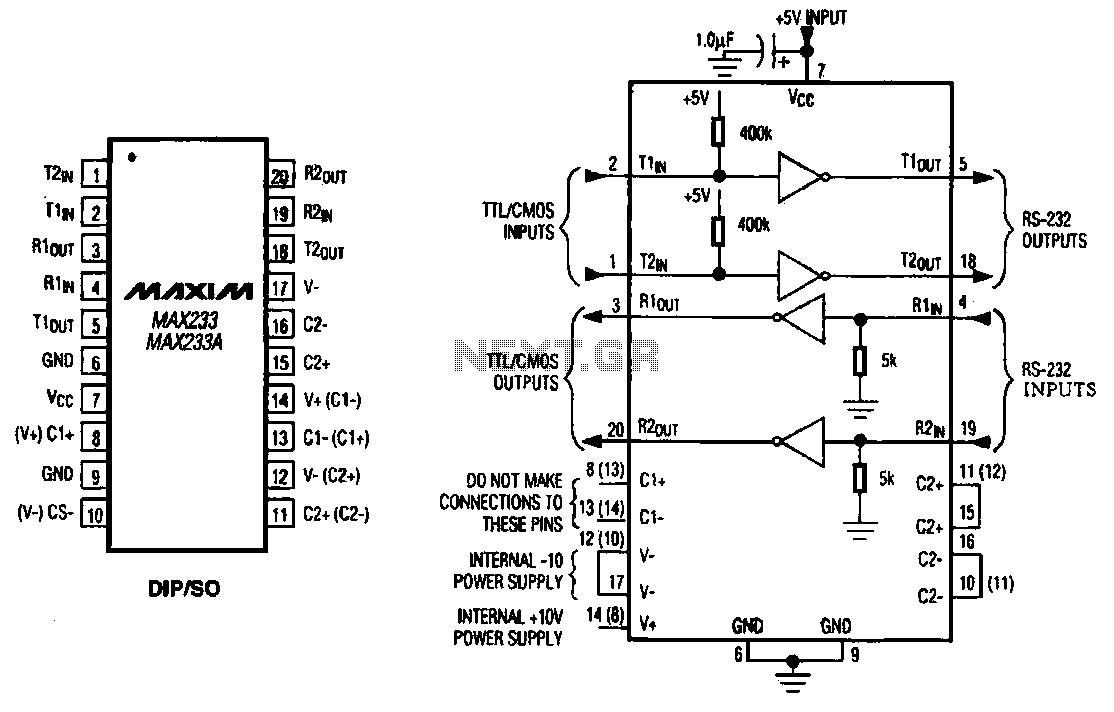
The MAX233 / 233A integrates multiple functions to enable effective communication between different digital devices. This circuit is particularly beneficial in applications requiring reliable data transfer, such as in embedded systems, consumer electronics, and multimedia applications.
The dual output configuration allows for simultaneous transmission of data to multiple devices, enhancing the versatility of the circuit. The dual input functionality ensures that the circuit can receive data from two sources, thereby increasing the efficiency of data handling.
The device operates with a voltage range that is suitable for various digital logic levels, making it compatible with a wide range of microcontrollers and digital signal processors. The integrated design minimizes the need for external components, simplifying the circuit layout and reducing overall system cost.
In terms of performance, the MAX233 / 233A is characterized by low power consumption and high-speed data transfer capabilities, which are essential for modern digital communication systems. The circuit's robust design ensures stability and reliability, making it a preferred choice for designers looking to implement effective data communication solutions in their products.
Overall, the MAX233 / 233A serves as a critical component in facilitating seamless data transmission in a variety of electronic applications, contributing to the development of efficient and compact digital systems.MAX233 / 233A multi-channel data interface circuit, the circuit has dual output, dual input of the driver circuit, for small digital products, multimedia equipment for data transmission.
Related Circuits
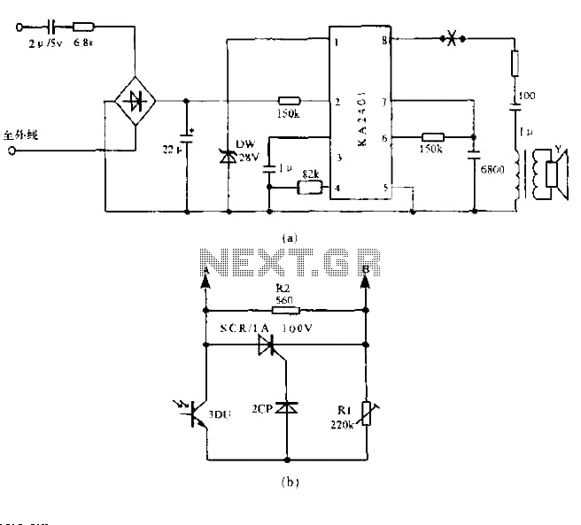
The circuit utilizes a standard telephone ringing circuit, KA2401, along with additional components to control lighting in response to a ringing signal. The light control circuit can be activated externally by AC when the ringing signal is received. The...
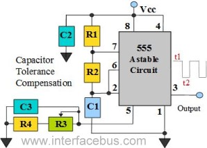
The 555 Timer is configured as an astable multivibrator. Additional components have been incorporated to enhance circuit operation. Upon powering the circuit, the 555 Timer will generate a square wave, determined by the values of Capacitor C1 and Resistors...
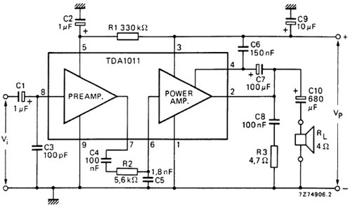
The following schematic illustrates the design of a 4 Watt Amplifier Circuit Diagram intended for portable radio applications, utilizing the TDA1011 integrated circuit from Philips Semiconductor. The 4 Watt Amplifier Circuit is designed to provide audio amplification in portable radio...
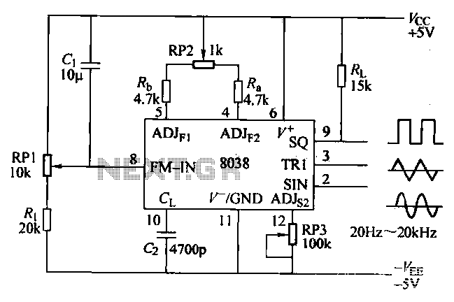
The ICL8038 function generator is an audio composition device that utilizes the ICL8038 integrated circuit. The resistance Ri potentiometer RP1 is used to determine the flow potential. Typically, the output is set to approximately 2Vcc / 3. Lowering the...
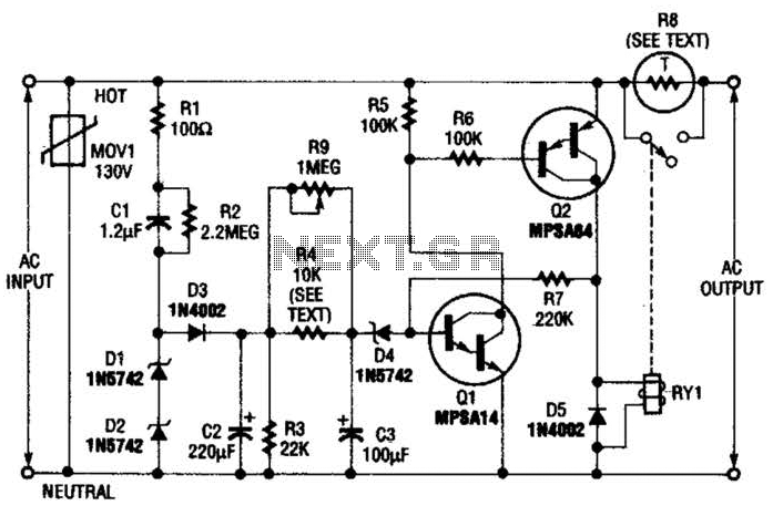
Q1 is an NPN Darlington transistor, and Q2 is a PNP Darlington transistor. MOV1 is a metal-oxide varistor, while R8 is a thermistor used for limiting inrush current. This circuit is designed to limit AC line current to a...
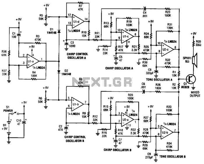
This circuit generates the sound of two canaries singing in a cage. Two LM324 quad amplifiers constitute seven oscillators. One oscillator serves as an on/off control, while the remaining six produce the sounds of two canaries. A 9-V supply...
Warning: include(partials/cookie-banner.php): Failed to open stream: Permission denied in /var/www/html/nextgr/view-circuit.php on line 713
Warning: include(): Failed opening 'partials/cookie-banner.php' for inclusion (include_path='.:/usr/share/php') in /var/www/html/nextgr/view-circuit.php on line 713