
MAX8903A charger circuit diagram
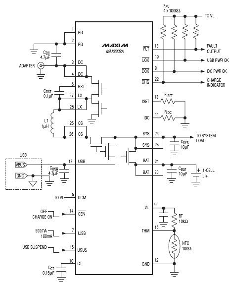
The charger integrated circuit (IC) is designed to efficiently manage power input from two sources: a DC input and a USB input. The DC input is capable of handling voltages between 4.15V and 16V, making it suitable for various applications where a stable and higher voltage is required. The inclusion of a protection feature that allows for a maximum input voltage of 20V ensures that the circuit remains safe from overvoltage conditions, which could potentially damage the IC or connected components.
On the other hand, the USB input is optimized for lower voltage applications, operating within a range of 4.1V to 6.3V. This range is typical for USB-powered devices, allowing for compatibility with standard USB power supplies. The protection limit of 8V serves as a safeguard, preventing damage from voltage spikes or surges that may occur during operation.
Incorporating both input options allows for versatility in design, making this charger IC suitable for a wide range of electronic devices. The ability to switch between DC and USB power sources enhances the usability of the device, providing flexibility in power management.
Additional design considerations may include the implementation of filtering capacitors at the input to smooth out voltage fluctuations, as well as thermal management solutions to dissipate heat generated during operation. Proper layout techniques, including trace width calculations and grounding strategies, will also contribute to the overall performance and reliability of the circuit.The DC input for this charger ic operates from 4. 15V to 16V with up to 20V protection, while the USB input has a range of 4. 1V to 6. 3V with up to 8V protection. 🔗 External reference
Related Circuits
The current feedback operational amplifier maintains a consistent bandwidth even when the open-loop gain is altered. This characteristic makes it particularly suitable for applications in video signal amplification and the driving circuits of video cables. The accompanying diagram illustrates...

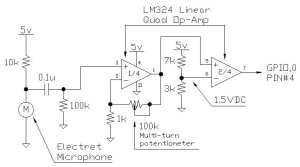
When the comparator's output transitions from low to high, the rising edge of the output pulse, differentiated by the Cl/Rl chain, activates Ql. This action blocks the comparator via its strobing input and maintains its output state for a...
Instructions for creating a Clap-Clap On/Clap-Clap Off switch circuit. This guide provides the necessary information for constructing a clap-activated switch. The Clap-Clap switch circuit is an innovative design that utilizes sound activation to control electronic devices. The primary components of...
The program utilizes the internal 4 MHz oscillator of the PIC16F628 microcontroller in a two-input alarm circuit. The two-input alarm circuit designed with the PIC16F628 microcontroller leverages the internal 4 MHz oscillator to provide a stable clock signal for operation....
Creating circuit boards can be a challenging task. It requires designing a schematic, testing it on a breadboard, laying out the board, and finally printing and etching the board. Fortunately, Fritzing offers a solution. Fritzing is a free, open-source...
The White's Classic I was a straightforward and user-friendly metal detector, making it suitable for entry-level enthusiasts. It featured a simple design with only an on/off switch and a discriminator adjustment knob. Although it lacked depth, it was capable...
Warning: include(partials/cookie-banner.php): Failed to open stream: Permission denied in /var/www/html/nextgr/view-circuit.php on line 713
Warning: include(): Failed opening 'partials/cookie-banner.php' for inclusion (include_path='.:/usr/share/php') in /var/www/html/nextgr/view-circuit.php on line 713