
MC14093 pulse width modulation controller circuit design

The MC14093 IC is a versatile component that integrates multiple NAND gates with Schmitt trigger characteristics, allowing for stable operation in noisy environments. The Schmitt trigger configuration provides hysteresis, which is beneficial in PWM applications as it allows for clean transitions between high and low states, minimizing the risk of oscillation.
In designing the PWM circuit, the input pins (8, 9, 12, and 13) are crucial for setting the logic levels that control the output behavior. These pins, when connected to ground or the positive supply voltage, determine the triggering conditions for the NAND gates. The output pins (10 and 11) can be configured to drive a load, such as a small motor, with the PWM signal, effectively controlling its speed.
The adjustable speed feature of the PWM controller is achieved by manipulating the duty cycle of the output signal. This can be done by varying the resistance or capacitance in the timing network associated with the NAND gates. The maximum RPM being two-thirds of the supply voltage indicates that the controller is designed for efficiency, ensuring that the motor operates within safe limits.
In applications where RFI could affect circuit performance, the inclusion of a ferrite bead on the gate of Q1 serves to suppress high-frequency noise. This is particularly important in PWM applications, where rapid switching can generate interference that may disrupt other electronic devices.
For motors with specific requirements for rapid switching, the use of a Schottky diode is recommended. This type of diode has a lower forward voltage drop and faster switching capabilities compared to standard diodes, making it suitable for high-frequency applications. Proper selection of the diode specifications is essential to ensure reliable operation and prevent damage to the motor or the PWM circuit.
Overall, this PWM controller circuit utilizing the MC14093 CMOS IC is a practical solution for speed control in various electronic projects, combining simplicity with effective performance.Using a MC14093 CMOS type IC, a quad 2-input NAND Schmitt trigger circuit can be designed a very simple pulse width modulation circuit controller electronic project. This pulse width modulation controller electronic project is very simple and require few external electronic parts.
The speed is adjustable from 0-max. Max rpm is 2/3 the supply vol tage. Supply voltage that can be used in this project can be between 3 and 18 volt. MC14093 CMOS type IC can be directly interchanged with the MC14011 CMOS IC. Input pins 8, 9, 12, and 13, need to be connected to Gnd. or `V+`. Output pins 10 & 11 are left floating. Maximum current draw, with the components shown, is approximately 220 mA max using a small type motor. To minimize RFI (Radio Frequency Interference), put a Ferrite Bead on the gate of Q1. A schottky diode of proper specs may be required for some motors which require faster switching. 🔗 External reference
Related Circuits
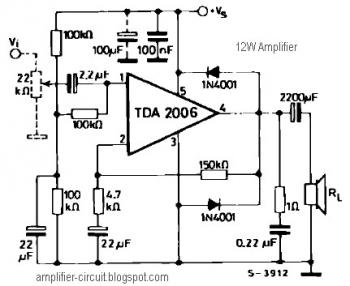
The power amplifier IC TDA2006 provides high output current and has very low harmonic and cross-over distortion. Furthermore, the device incorporates an original (and patented) short circuit protection system that automatically limits the dissipated power to keep the working...
A microprocessor cannot drive a motor directly since it cannot supply enough current. Instead, an interface circuit is required so that the motor power is supplied from another source, with only control signals derived from the microprocessor. This interface...
This simple circuit can be utilized to activate various devices, such as microcontrollers, relays, secret alarms, or robot applications. It can also be used to turn on LED1, which remains illuminated as long as the metal plate is touched....

A high power joule thief circuit is explained in this post, which can be constructed by any new hobbyist. Here is the simplified drawing of the radiant joule thief battery charger. The inductor was wound with many turns until...

A cadmium sulfide photoresistor (CD1) fingertip can be detected through the filter. CD1 forms part of the sense amplifier feedback network. A section of the sense amplifier (ICA) produces weak signals that may be further amplified by ICB. These...

This FM IF MW radio receiver circuit schematic utilizes the LA1260 integrated circuit (IC), which is suitable for AM and FM radio receiver electronic projects. The LA1260 incorporates numerous functions and features essential for radio receiver applications, including a...