
MC2833 radio transmitter Typical application circuit
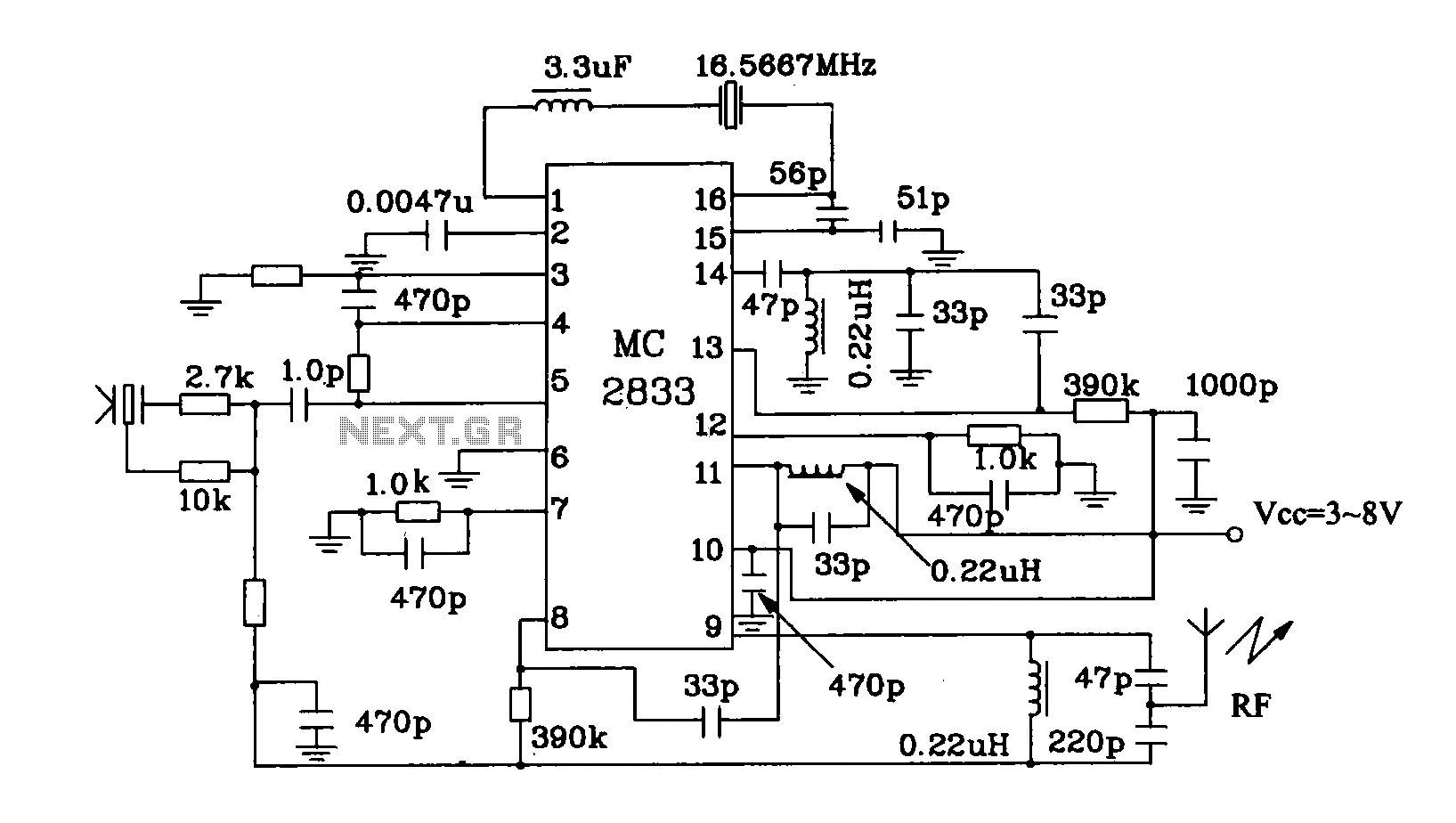
The MC2833 and MC2831 integrated circuits are designed for efficient radio frequency transmission applications. The circuit operates at a frequency of 49.7 MHz, which is suitable for various short-range communication tasks. The primary function of this circuit is to modulate audio signals onto a carrier wave, allowing for the transmission of information over radio waves.
The circuit typically includes an oscillator stage that generates the desired frequency, a modulator stage that combines the audio input with the carrier wave, and a power amplifier stage that boosts the signal strength for effective transmission. The antenna connected to the output of the power amplifier radiates the modulated signal into the surrounding environment.
In practical applications, the MC2833 and MC2831 circuits can be used in wireless microphones, remote controls, and other devices that require reliable radio communication. The design ensures minimal distortion and efficient power usage, which are critical for maintaining signal integrity and extending battery life in portable devices.
For optimal performance, careful consideration must be given to the layout of the circuit board, component selection, and tuning of the oscillator to achieve the desired frequency stability and output power. Additionally, proper shielding and grounding techniques should be implemented to minimize interference and enhance the overall performance of the transmitter circuit.MC2833 MC2831 radio transmitter dedicated circuit is improved.Radio transmitter typical application circuit this circuit generates a high frequency 49.7MHz signal transmitted by the antenna out.
Related Circuits
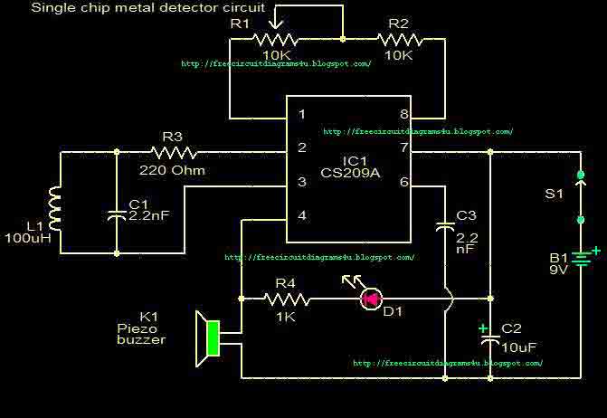
This circuit is a single chip metal detector. Actually, we can use this one to detect metals. Especially, you have seen some army soldiers keep something to detect metals. That equipment has been made through this circuit. So you...
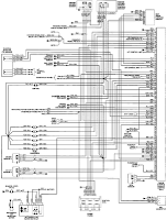
The electrical wiring diagram for the 1993 VW Passat includes the Engine Control Module, Automatic Control Unit, and Automatic Solenoid. This diagram illustrates the connections and wiring between various components of the vehicle's system, such as the multi-function switch,...
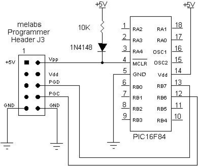
The EPIC Plus Programmer, also known as the Serial Programmer, USB Programmer, or U2 USB Programmer, can be utilized for in-circuit serial programming of serially programmable PIC Microcontrollers via the 10-pin expansion header J3. Connections for Vpp, RB6, RB7,...

This circuit for a laser door alarm operates on the principle of laser beam interruption. A low-cost laser pointer serves as the light source. When an object disrupts the laser beam, an alarm is triggered for a few seconds....
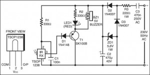
The following circuit illustrates an IR Remote Control Tester Circuit. Features include that transistor T1 conducts during the negative pulse period, and there is a data output pin. The IR Remote Control Tester Circuit is designed to verify the functionality...
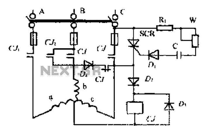
AC contactor controls suction units, with the motor activated simultaneously. A pair of contacts (CJ1) short-circuits the thyristor (SCR), turning it off. The contactor (C) is influenced by the diode's DC voltage. In the positive half-wave power cycle, the...
Warning: include(partials/cookie-banner.php): Failed to open stream: Permission denied in /var/www/html/nextgr/view-circuit.php on line 713
Warning: include(): Failed opening 'partials/cookie-banner.php' for inclusion (include_path='.:/usr/share/php') in /var/www/html/nextgr/view-circuit.php on line 713