
mic 702 mictronics schematic diagram
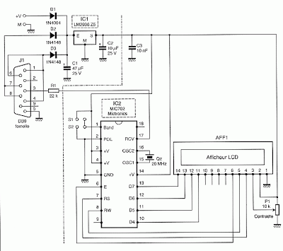
The MIC 702 circuit provides a robust solution for interfacing standard LCD displays with serial communication systems. The design allows for seamless conversion from parallel to serial, which is particularly advantageous in applications where space and wiring complexity must be minimized. The choice of a low-dropout regulator ensures that the circuit maintains efficient power management, which is critical in battery-operated devices. The use of a simple resistor for level shifting simplifies the design, reducing the need for additional components, which can lead to increased reliability and reduced manufacturing costs.
In terms of implementation, the circuit should be laid out carefully to minimize noise and interference, particularly in the data lines. Proper decoupling capacitors should be placed near the power pins of the MIC 702 to ensure stable operation. Additionally, it is advisable to use twisted pair wiring for the serial connection to further reduce electromagnetic interference, especially in environments with high-frequency noise. The selection of the appropriate baud rate is crucial for ensuring reliable data transmission, and careful consideration should be given to the specific requirements of the application when configuring the POL pin to match the data format being used.
Overall, the MIC 702 circuit represents an efficient and effective means of interfacing parallel LCD displays with serial communication systems, enhancing the versatility of display solutions in a variety of electronic applications.To convert a standard LCD interface parallel to serial interface model, use a microcontroller or a dedicated circuit such as the MIC 702 Mictronics you can download the complete data sheet and French by clicking this link. This is a circuit specially designed to transform the parallel interface and LCD display logic integrated asynchronous serial
interface standard. Its implementation is very simple as shown in the diagram below. The MIC 702 is connected directly to the display with which it is perfectly compatible. Notice the connection with only 4 data bits of high weight since the MIC 702 operates in the display mode twice 4 bits. PC side, the connection with the serial output of the PC does not involve any level converter for RS 232 TTL, this role being played by the only resistor R1 22 ohm whose presence is essential.
BAUD The tab allows you to choose the operating speed of the circuit between two speeds: 9600 bps up with S1 or S2 with 2400 baud up. The leg POL allows the circuit to interpret the serial data as direct or inverted. As it is in direct RS232 link should be link this foot to ground to indicate the MIC 702 that receives data reversed.
Linkage to +5 volts it would receive direct evidence as would be the case if we wanted to use this circuit with a Basic Stamp example. Subject to use a display not backlit, the total consumption of the circuit is low enough that it can take its power directly from the output control signals to the RS 232.
It is the role of diodes D2 and D3 associated with IC1, which is a regulator with low dropout voltage and low consumption. If you insist on using a backlit display, it is possible that consumption of its single backlight exceeds the possibilities of the PC`s serial port.
You can use an external power supply via the diode D1. A voltage of 9 volts at a flow rate of a hundred mA appropriate. 🔗 External reference
Related Circuits
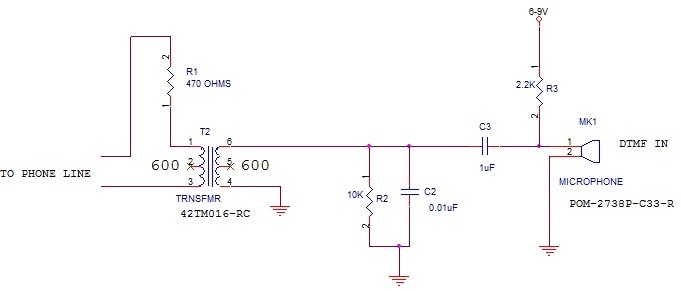
What type of microphone or mouthpiece can be used to connect to a POTS (Plain Old Telephone Service) telephone line to send DTMF (Dual-Tone Multi-Frequency) tones only, without transmitting voice? Is a standard microphone suitable, or must it be...
Each component of the circuit is represented in a simple block form with corresponding labels for identification, using no special symbols or language. The interconnections between these components are depicted by solid lines. The block diagrams can be read...
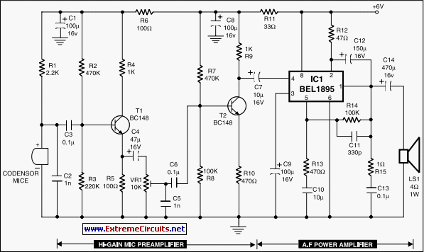
The compact, low-cost condenser microphone audio amplifier described here delivers good-quality audio output of 0.5 watts at a supply voltage of 4.5 volts. It can be utilized as part of intercom systems. This audio amplifier circuit is designed to enhance...
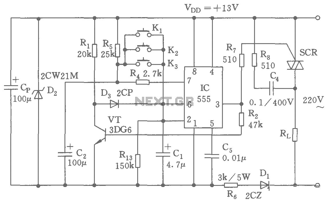
The switching circuit consists of a buck rectifier circuit, a bistable trigger circuit, and a thyristor control circuit, enabling remote control for electrical equipment to be turned on or off. The buck rectifier circuit supplies the controller with a...
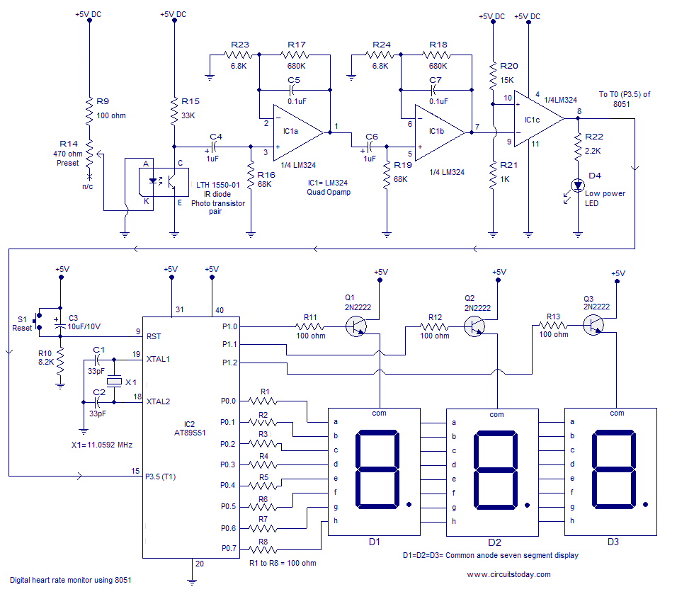
Heart rate monitor using an 8051 microcontroller. It measures the heart rate from the fingertip using an IR diode and phototransistor pair (Photoplethysmography). The AT89S51 microcontroller is utilized in this application. The heart rate monitor circuit operates based on the...
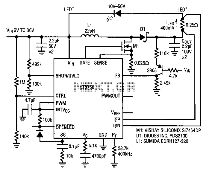
Common LED driver requirements include a wide and overlapping range of LED string voltages and input voltages. Many designers prefer to use an LED driver circuit that accommodates various battery power sources and multiple LED strings. This universal configuration...
Warning: include(partials/cookie-banner.php): Failed to open stream: Permission denied in /var/www/html/nextgr/view-circuit.php on line 713
Warning: include(): Failed opening 'partials/cookie-banner.php' for inclusion (include_path='.:/usr/share/php') in /var/www/html/nextgr/view-circuit.php on line 713