
Micro mixer circuit by TA7137
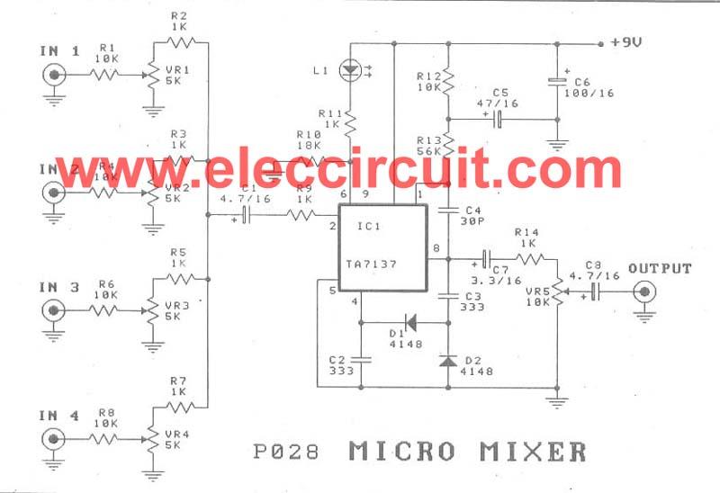
The detailed parts include:
- IC1: TA7137 pre-amplifier for recording or playback with ALC transistor for tape recorders.
- D1, D2: 1N4148 diodes rated at 75V, 150mA.
- L1: LED, 2x5 mm.
- R1, R4, R6, R8, R12: 10K, 1/4W resistors.
- R2, R3, R5, R7, R9, R14: 1K, 1/4W resistors.
- R10: 18K, 1/4W resistor.
- R11: 1K, 1/4W resistor.
- VR1, VR2, VR3, VR4: 5K-10K potentiometers.
- VR5: 10K potentiometer.
- C1, C8: 4.7uF, 16V electrolytic capacitors.
- C2, C3: 0.0033uF, 50V polyester capacitors.
- C4: 30pF, 63V polyester capacitor.
- C5: 47uF, 16V electrolytic capacitor.
- C6: 100uF, 16V electrolytic capacitor.
- C7: 3.3uF, 16V electrolytic capacitor.
To construct the circuit, all components must be installed correctly on the PCB as per the schematic in Figure 2. Once assembled, the circuit can be housed in a box for ease of use. During installation, it is recommended to detach potentiometer VR5 from the PCB and secure the PCB to the box using the mounted potentiometers VR1 to VR4. Additionally, the LED L1 should be positioned outside the box for visibility. The wiring to the equipment jacks and the PCB should be done systematically to ensure proper functionality.If you are looking for a micro mixer circuit that create a simple, affordable, small and compact, and be usable versatile, must be this circuit. We can use to mix up to four input channels such as the microphone signal, FM Tuner, AUX and Other signals, As circuit shown in Figure 1.
How it works. The input signal Input signal in each channel is entered through R1, R4, R6, R8, respectively, to potentiometer VR1-VR4. which is Adjustment value of Signal in each channel is the right size. Then is entered through a R2, R3, R5, R7 in together, and then pass through C1, R9 to input of IC1. – The IC1(TA7137) is amplifier a signal that was introduced all together, Until the output signal at pin 8 through C7.
– The R14 and VR5 It is the adjust strength of the total output signal. – The C3, C2, D1, D2 are feed back circuit for control gain of circuit to has level constant output signal. – The LED L1 is a signal meter display that it flashes by the signal strength of the input voltage applied to the circuit.
The detail parts. IC1_________________________________TA7137 PRE-AMPLIFIER(RECORDING OR PLAYING-BACK WITH ALC TRANSISTOR FOR TAPE RECORDER) D1, D2______________________________1N4148___75V 150mA Diodes L1__________________________________LED 2×5 mm R1, R4, R6, R8, R12____________________10K____1/4w Resistors R2, R3, R5, R7, R9, R14________________1K____1/4w Resistors R10_________________________________18K____1/4w Resistors R11_________________________________1K____1/4w Resistors VR1, VR2, VR3, VR4__________________5K-10K___Potentiometer VR5________________________________10K SW. C1, C8______________________________4.7uF 16V____Electrolytic Capacitors C2, C3______________________________0.0033uF 50V___Polyester Capacitor C4_________________________________30pF 63V___Polyester Capacitor C5_________________________________47uF 16V___Electrolytic Capacitors C6_________________________________100uF 16V____Electrolytic Capacitors C7_________________________________3.3uF 16V____Electrolytic Capacitors How to builds We install all the components on the PCB correctly completed.
According to circuit in Figure 2. When finishedwe can install it in a box ready, for ease of use. In installed in the box, should be unloaded VR5 from PCB to hold separate. We can hold PCB to the box, with holding the potentiometer VR1-VR4 to box there. Then we remove the LED L1 out away, to hold at the box. And then we wiring to the equipment Jack and the PCB orderly.
Related Circuits
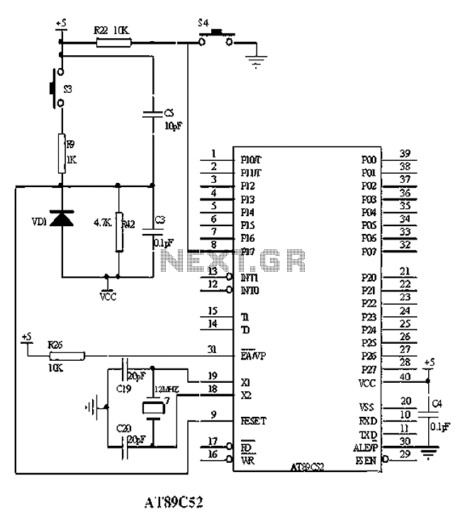
The American Atmel AT89C52 is a low-voltage, high-performance CMOS 8-bit microcontroller chip that contains 8KB of rewritable program memory and 256B of random access data memory (RAM). Atmel's high-density devices utilize non-volatile memory technology and are compatible with the...
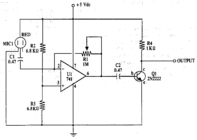
Amplifier circuit for electret microphones (condenser microphones). It amplifies the audio signals picked up by the electret microphone using a 741 op-amp and a 2N2222 transistor. The amplifier circuit designed for electret microphones utilizes a combination of a 741 operational...
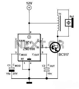
Zetex Semiconductors offers a siren driver integrated circuit (IC) known as the ZSD100, which is designed for use in alarm systems for vehicles and model crafts. By incorporating just a few additional components, as illustrated in the accompanying diagram,...
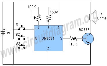
The circuit under discussion is a four-siren sound generator utilizing the UM3561 integrated circuit (IC), which is a low-power CMOS device. Four distinct sounds can be generated by activating switches S1, S2, and S3. This circuit is versatile and...
I have been researching a "mystery circuit" and I cannot determine its name. Assistance is requested. The inquiry pertains to an unidentified electronic circuit, often referred to as a "mystery circuit." Such circuits can encompass a wide range of configurations...
A lot of friends asked me to draw a more shrunk circuit 2-ch mixer, which will contain also, operation CROSSFADER. The circuits can be modified and added also other channels, repeating basic that I give. It can be added...