
Micro Power Transmitting Station
The AM transmitter project involves several critical components and stages that contribute to its overall functionality. The circuit design typically includes an oscillator circuit, modulator, amplifier, and antenna. The oscillator generates the carrier wave at the desired frequency, which is subsequently modulated with the audio signal to be transmitted. The modulator can be implemented using various methods, such as amplitude modulation (AM), where the amplitude of the carrier wave is varied in accordance with the audio input.
The choice of the carrier frequency is crucial for ensuring minimal interference with existing broadcasting stations. In this case, the decision to operate at 960 kHz was made after careful consideration of the surrounding radio frequency environment. The design must also comply with FCC regulations to ensure that the transmitter operates within legal limits for micro power stations, which typically have restrictions on power output and transmission range.
Construction of the transmitter involves assembling the components on a protoboard, allowing for adjustments and testing. This phase includes soldering connections, ensuring that all components are correctly oriented and connected. Testing the circuit involves using an oscilloscope to verify the waveform and a strength meter to measure the output signal strength, ensuring that it meets the required specifications.
Once the transmitter is operational, further testing is necessary to assess its range and audio quality. This may involve broadcasting a signal and measuring the reception quality at various distances. Any necessary adjustments can be made to improve performance, ensuring that the device operates effectively within the defined parameters.
Overall, the project encapsulates the practical application of theoretical knowledge gained throughout the electronics program, emphasizing the importance of hands-on experience in understanding circuit design and implementation.The purpose of this report is to provide background and findings or our senior project. We will discuss four steps that we used to complete our final project. The four steps of our project were research and development, design, construction, and test & acceptance. Building an AM transmitter allowed our group to apply our circuit design, fabricatio n skills, logical troubleshooting practices, and to prove theory of operation. It is our intent to show the step by step process of how to build and operate a micro power AM transmitter station. When you have read our report, our findings will show that this project was more than throwing parts on to a circuit board.
We will show how, what, why, and when as directed by the instructor and give reason and understanding to our approach. Anyone that reads this report will gain the knowledge of how to design and implement a totally legal micro power AM transmitter station.
We decided on a micro power transmitter station because it allowed us to utilize all the skills that we have acquired attending Devry University. We had many labs throughout our studies exploring the principles and theories behind digital and analog devices.
We wanted to construct a project that incorporated several key elements of our electronics program. For this project we would implement a component level construction that we would improve through test and acceptance to an industry standard following guidelines mandated by the FCC. With an improved design and a little patience, we would able to produce a very useful device that could be set up to broadcast any message of the operator ’s choice or music to a small receiving area.
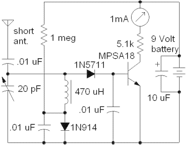
The exact requirements to classify our project as a micro power transmitter station. Our team was formed because of our mutual experiences in other labs throughout our degree. The first meeting was used to decide on a project that we would mutually enjoy but yet challenge our new skills. After hours of combing the Internet, we came up with several different proposals. The design that we all agreed on was and AM transmitter with an additional useful tool to be used in conjunction called a strength meter.
With very helpful design ideas obtained from, we began calling different manufacturers of the parts we would need to complete the project. Our first decision was finding a usable frequency that we would be transmitting our broadcast on. Our decision was on a carrier frequency of 1. 64 Megahertz, because it was very available and not close to any major broadcasting stations. We called 3 different manufactures of crystal oscillators, but were discouraged by either the prices or the length of time we would have to wait for manufacturing and shipping.
After several trips to a local electronics supply store, Supertronics, we decided on a lower frequency of 960 kilohertz. Although there is a major broadcasting station, KJR 950, nearby we are isolated by the shielding of the school from outside interferences.
With our project decisions and task planned for each member of the team, we were on our way to designing the project. We had our design in hand after the research and development phase of the project. In week 2 of the semester we began looking for available programs to use to put our project on the computer.
We felt it was imperative to simulate our idea using multisim or a comparable program at first. After several attempts we found that our transmitter, with its very particular operation, did not simulate very well on the computer. We decided to take an inventory of the parts that we already had in our school toolbox and found that we would need to buy the majority of the parts.
The team decided to put the circuit on a protoboard where we could get a rough idea of how well it would operate. Several key components such as high output transistors and the pot core were special ordered on the internet.
While we waited for the delivery 🔗 External reference
Related Circuits

The digital camera power supply utilizes the MAX1565 chip, which features a five-channel power supply configuration. The chip generates various signal widths and control circuits tailored to meet the DC voltage and current requirements of the digital camera. The...
PIC microcontrollers are a highly useful and versatile component for various electronic projects. They are affordable and readily available. PIC microcontrollers are embedded systems that serve as the central control unit in a wide range of electronic applications. Their architecture...

As found in SLAA458, the revised pulse oximeter application, an image of the USB schematic is attached, which is used to output collected data. There are a few questions regarding this schematic: 1) What do J3 and J6 correspond...

Class-A is ideal for this application, since headphones are such an intimate way of listening. An amplifier for 'phones should be as clean and free from crossover distortion as possible, and must also be quiet. A background of hiss...
This chapter includes circuit diagrams for various power supplies designed for pulsed solid-state lasers. It features units that are compatible with the widely used Hughes ruby and YAG rangefinder laser assemblies, one utilizing the flash from a disposable pocket...

A power transistor can be utilized to supply a high-powered Zener voltage from a low-wattage Zener diode. A 400 mW Zener diode can be employed in applications requiring a 10-watt Zener, or a 1 W Zener can be used...