
Micro-sized-amplifier
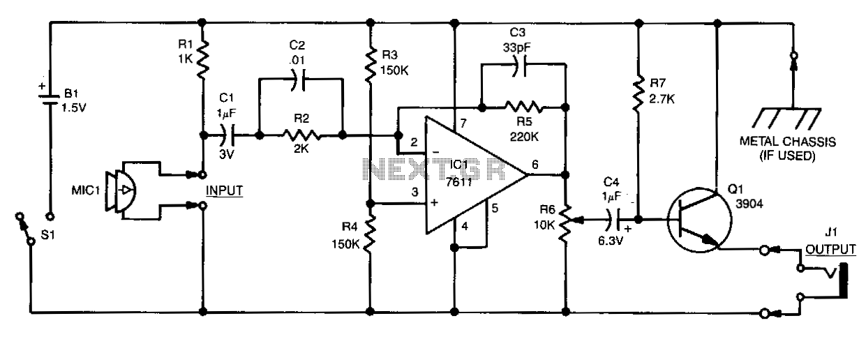
Sound detected by the electret microphone MIC1 is fed to the input of IC1 through resistor R2 and capacitors C1 and C2. Resistors R2 and R5 determine the overall gain of the stage, while C2 partially influences the amplifier's frequency response. A single-ended power supply is required for proper operation. Resistors R3 and R4 create a null condition equal to half the power supply voltage at the non-inverting input of IC1. The output of IC1 is transferred to the emitter-follower amplifier Q1 via the volume control resistor R6. The high-impedance input and low-impedance output characteristics of the emitter-follower match the moderately high-impedance output of IC1 to a low-impedance headphone load.
The circuit described functions as a basic audio amplification system, designed primarily for interfacing an electret microphone with a headphone output. The electret microphone (MIC1) converts sound waves into an electrical signal, which is then conditioned by the subsequent components. The signal from MIC1 is routed through resistor R2, which serves to limit the current and set the input impedance to IC1, an operational amplifier.
Capacitors C1 and C2 play crucial roles in the circuit. C1 is typically used for AC coupling, ensuring that only the audio signal passes through to IC1 while blocking any DC offset that may be present. C2 serves a dual purpose: it contributes to the frequency response of the amplifier and helps stabilize the circuit by filtering out unwanted high-frequency noise.
The gain of the amplifier stage is determined by the ratio of resistors R2 and R5. By adjusting these resistors, one can increase or decrease the amplification level, allowing for customization based on the microphone's output level and the desired output level for headphones.
The configuration of resistors R3 and R4 is critical for setting a bias point at the non-inverting input of IC1. By creating a voltage divider, these resistors establish a reference voltage that is half of the power supply voltage. This configuration ensures that the operational amplifier operates within its linear range, preventing distortion of the amplified signal.
The output of IC1 is connected to an emitter-follower amplifier, Q1, which is characterized by its high input impedance and low output impedance. This configuration is essential for driving headphones, as it allows for the matching of the output from IC1 to the lower impedance of the headphone load. The volume control resistor R6 is integrated into this path, enabling the user to adjust the audio level before it reaches the headphones.
Overall, this circuit exemplifies a straightforward yet effective design for audio amplification, suitable for various applications where sound detection and amplification are required, such as in hearing aids, portable audio devices, or simple sound recording systems.Sound detected by electret microphone MIC1 is fed to IC1"s input through resistor R2, and capacitors Cl and C2. Resistors R2 and R5 determine the overall stage gain, while C2 partially determines the amplifier"s frequency response.
To ensure proper operation, use a single-ended power supply. R3 and R4 simulate a null condition equalto half the power supply"s voltage at IC1"s noninverting input. The output of IC1 is transferred to emitter-follower amplifier Ql via volume control R6. The high-Z-in/low-Z-out characteristic of the emitter-follower matches the moderately high-impedance output of IC1 to a low-impedance headphone load. 🔗 External reference
Warning: include(partials/cookie-banner.php): Failed to open stream: Permission denied in /var/www/html/nextgr/view-circuit.php on line 713
Warning: include(): Failed opening 'partials/cookie-banner.php' for inclusion (include_path='.:/usr/share/php') in /var/www/html/nextgr/view-circuit.php on line 713