
Microcontrolled Lab Power Supply
The displays are standard red 7-segment LEDs. They are multiplexed in software to simplify the circuit design. A set of 6 small PNP transistors activates each one in turn at about a 100 Hz scan rate.
Because of the nature of switching supplies, it is actually possible to get more amperes out of the unit than the transformer is rated for. I got over 4 amps out at 5 volts. As you increase the voltage, less current is available.
The software listing is included here along with the Object File, as is the Schematic. Like other projects shown on this site, you are welcome to use whatever information you want but this is not a step-by-step guide to making your own. Some of the parts used here were scrounged from the junk box and the values are unknown - they just seem to work.
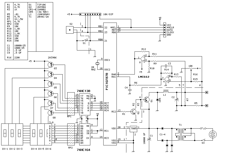
This electronic circuit operates as a programmable DC power supply, capable of delivering an adjustable output voltage between 0 to 20 volts with a maximum output current of 4 amps. The core of the design is the PIC16F870 microcontroller, which manages the power supply's operation through software-controlled voltage regulation. The microcontroller's analog inputs are utilized for real-time measurement of output voltage and current, allowing for precise control and monitoring.
The front panel features a simple user interface consisting of a push-button switch for power control and a rotary encoder for voltage adjustment. The push-button acts as a soft switch; the device remains powered even when in the off state, indicated by a dimmed display that maintains the last set voltage value. The rotary encoder allows users to fine-tune the output voltage in 0.1-volt increments, enhancing usability.
In terms of safety features, the unit includes a current cutout function that can be accessed by holding the push button for two seconds. This feature is crucial for preventing damage to the load or the power supply itself by completely shutting off the output when the set current limit is exceeded. The cutout mode is visually indicated on the display, providing clear feedback to the user.
The output voltage regulation is achieved using pulse width modulation (PWM), with the PIC16F870 generating PWM signals to control the power delivery effectively. This method allows for efficient conversion of input power to the desired output level. The visual output is provided via multiplexed red 7-segment LED displays, which are driven by a set of six PNP transistors operating at a scanning frequency of approximately 100 Hz. This multiplexing technique reduces the number of required connections and simplifies the overall circuit design.
The design's inherent characteristic of switching power supplies enables the unit to output more current than the transformer rating under specific conditions, particularly at lower output voltages. This feature allows for flexibility in usage but requires careful monitoring to avoid overloading the transformer.
Overall, this circuit represents a versatile solution for applications requiring adjustable DC power, combining efficient hardware design with user-friendly software control.This unit delivers 0 to 20 volts at up to 4 amps in 0.1 volt increments. The entire device runs on a PIC16F870 (about $3 in small quantities). This is basically a switching power supply with the voltage regulation done in software. The PIC used here has analog inputs (used to measure voltage and current) and hardware PWM (pulse width modulation) output used to control the power. Only two controls are used on the front panel - an 'on/off'' push button and a rotary encoder. The on/off button is a 'soft' control; the unit actually stays powered up all of the time. In the 'off'' mode, the display is blanked except for the far right decimal which acts as a standby indicator, and the voltage output is set to zero.
Also, while in this mode, the rotary encoder is not active so that the previously selected voltage will be maintained when the unit is powered back on. This design has a 'current cutout' which will turn off power completely. To access the cutout limit, turn the unit on, then hold down the button for about 2 seconds. The left display shows 'ALI' and the right displays shows the current. To go back to normal operation, hold button for 2 seconds again. The displays are standard red 7-segment LED's. They are multiplexed in software to simplify the circuit design. A set of 6 small pnp transistors activates each one in turn at about a 100 hz scan rate. Because of the nature of switching supplies, it is actually possible to get more amperes out of the unit than the transformer is rated for. I got over 4 amps out at 5 volts. As you increase the voltage, less current is available. The software listing is included here allong with the Object File,as is the Schematic.Like other projects shown on this site, you are welcome to use whatever information you want but this is not a step-by-step guide to making your own.
Some of the parts used here were scrounged from the junk box and the values are unknown - they just seem to work. 🔗 External reference
Related Circuits
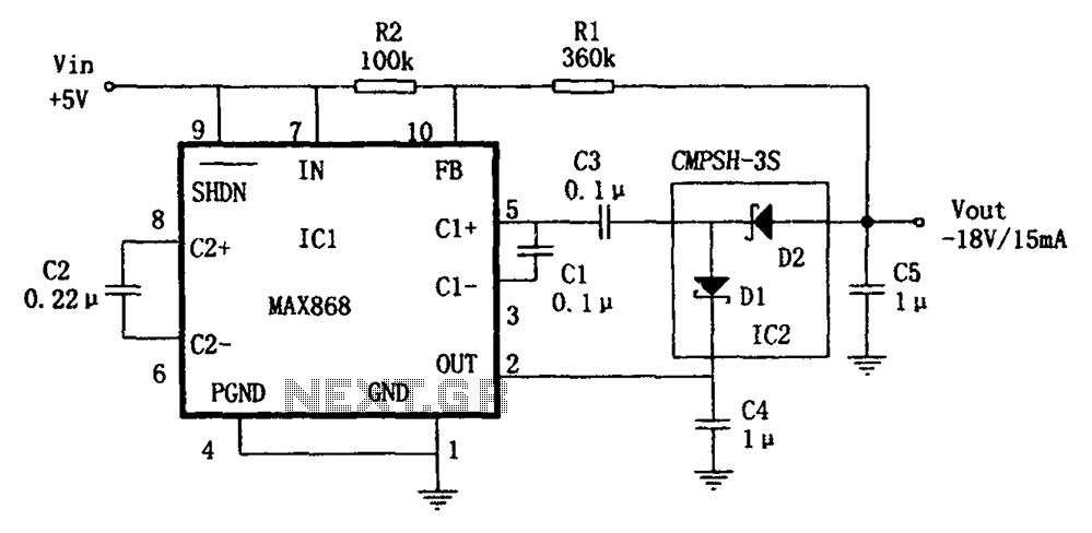
The circuit utilizes the IC1 MAX868 and CMPSH-3S to create a quadruple voltage DC/DC converter power supply. The IC1 MAX868 is an inverting charge pump regulator integrated circuit that can generate an output voltage of up to -2VIN, with...
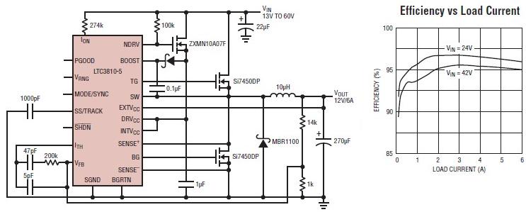
The LTC3810-5 synchronous step-down switching regulator controller can be used to design a simple and efficient 12-volt switching power supply electronic project with minimal external components. This controller is capable of stepping down voltages from up to 60V, making...
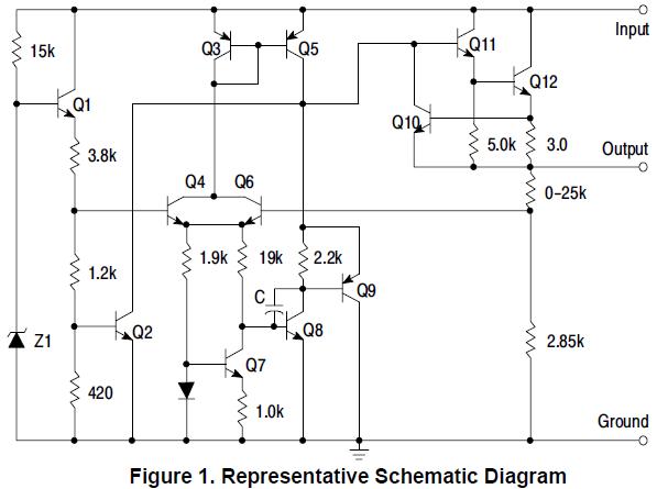
MC78L15ABPG positive voltage regulator, 100mA, TO-92 The MC78L15ABPG is a low-dropout (LDO) voltage regulator designed to provide a stable output voltage of 15V with a maximum output current of 100mA. This device is packaged in a TO-92 form factor, which...
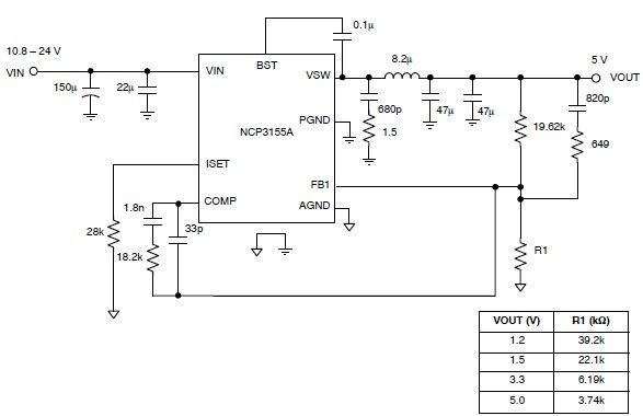
This 5-volt regulated power supply circuit project is designed using the NCP3155 DC-DC switching regulator, which features fully integrated power switches and comprehensive fault protection. The circuit requires only a few external electronic components and delivers a fixed output...
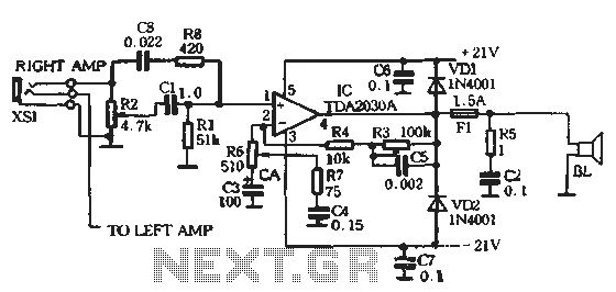
The circuit comprises two main components: the Lisheng power amplifier and the rectifier filter section. The stereo audio power amplifier circuit diagram, depicted in Figure 5-85, illustrates only one channel, with the other channel being identical. The audio signal...
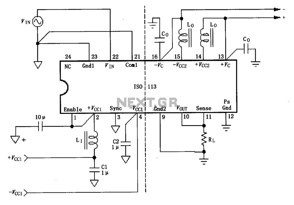
The basic connection circuit for the ISO113 signal and power supply is illustrated. Each power supply terminal must include a bypass filter. If the output current from the isolated power supply exceeds 15mA, it is advisable to utilize an...