
MicroFlash Schematic
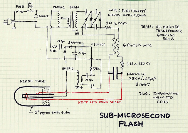
The two resistors serve dual purposes. Firstly, they limit the current to a lower value in case of accidental contact with the circuit. Secondly, when the flash is activated, the main capacitor behaves like a short circuit to the power supply, and these resistors restrict the short circuit current. A 10kV @ 23mA oil burner transformer was found. The question arises whether running a single doubling stage for 20kV will suffice for the tube or if it would be more beneficial to acquire a 50kV capacitor and double the voltage twice for 40kV. Additionally, there is curiosity about the choice of high voltage and small capacitance (35kV, 0.03 µF = 1.05mC, or 18.38J stored) versus low voltage with larger capacitance (for example, 450V, 1mF = 450mC, or 101.3J stored). It is suggested that the energy requirement may be lower due to the proximity of the subject, and whether this affects the flash duration. The capacitance is identified as a limiting factor for pulse width. Edgerton's findings indicate that the resistance of the spark flash is approximately 10 ohms, leading to the conclusion that the RC time constant limits the pulse width. For instance, a 1µF capacitor would yield a pulse of about 10µs under equivalent conditions, while a 0.03µF capacitor would produce a pulse width of 0.03µF multiplied by 10 ohms, resulting in 300ns. Questions arise regarding the efficacy of generating a good spark with a 450V capacitor, as these voltages typically utilize low-pressure xenon to produce a flash, which has a long duration, thus extending the flash length. The combination of small capacitance and high voltage is utilized to achieve a brief pulse. Most microsecond flash units employ this method, despite the challenges posed by high voltage.
The circuit design incorporates two resistors that limit the current, ensuring safety and preventing damage during accidental contact or flash activation. The resistors are strategically placed to manage the current flowing from the power supply to the main capacitor, which is critical in high-voltage applications. The choice of a 10kV @ 23mA transformer indicates a robust power source capable of driving the circuit.
In high-voltage flash applications, the capacitor's voltage rating and capacitance value are crucial in determining the energy storage and flash duration. The selection of a high-voltage capacitor (35kV, 0.03 µF) allows for a significant voltage to be stored while maintaining a low capacitance, which is essential for generating short, intense flashes. This configuration is guided by the need for a rapid discharge to produce a brief flash, as longer pulses are typically undesirable in high-speed imaging applications.
The discussion about whether to use a single doubling stage for 20kV or a 50kV capacitor for a double voltage approach reflects considerations of efficiency and the specific requirements of the application. Doubling the voltage can lead to increased energy storage, but it may also introduce additional complexity and safety concerns.
The relationship between capacitance, resistance, and pulse width is fundamental in designing circuits for flash applications. The RC time constant, determined by the resistance of the spark flash and the capacitance of the capacitor, dictates the maximum pulse width achievable. This relationship is critical for optimizing the performance of flash units, particularly when using low-pressure xenon, which enhances the duration of the flash.
Overall, the design choices made in this circuit reflect a balance between achieving high voltage, managing energy storage, and ensuring safety during operation. The careful selection of components and their arrangement in the circuit are crucial for optimizing performance in high-voltage flash applications.These two resistors have two functions. One, if I touch the circuit by accident, they limit the current to a lower value. Two, when the flash fires, the main capacitor looks like a short circuit to the power supply. These two resistors limit the short circuit current. I just found myself a 10kV @ 23mA oil burner tranfsormer in the garage. Ya think running a single doubling stage for 20kV will be enough for the tube or would it be better to get a 50kV cap and double the voltage twice for 40kV Excellent drawing, thanks! Is there any reason why you went for high voltage & small cap (35kV. 03 µF = 1. 05mC i. e. 18. 38J stored), rather than small voltage and much larger capacitance (for instance a 450V 1mF = 450mC i.
e. 101. 3J stored) Is it only because you do not require much energy since your subject is pretty close Does it have an impact on the flash duration The limiting factor for pulse width is the capacitance. Edgerton found out that the resistance of the spark flash is about 10 ohms. From this is follows that the RC time constant limits the pulse width. For example, your 1microfrad cap would give a pulse of about 10usec, all other things being equal. A. 03uF cap gives a pulse width of 10ohms*. 03uF or 300nsec. And I am not sure how you could get a good spark off of a 450V cap. These voltages use low pressure xenon to get a flash and the xenon light is very long lived, further increasing the flash length.
So the small capacitance, high voltage combination is used to get a short pulse. All the microsecond flash units that I know about use this technique. It is a pain because of the high voltage, but it works. [url= [url= Schematic[/url] by [url= on Flickr [url= [url= Schematic[/url] by [url= on Flickr [url= [url= Schematic[/url] by [url= on Flickr [url= [url= Schematic[/url] by [url= on Flickr [url= [url= Schematic[/url] by [url= on Flickr [url= [url= Schematic[/url] by [url= on Flickr
The circuit design incorporates two resistors that limit the current, ensuring safety and preventing damage during accidental contact or flash activation. The resistors are strategically placed to manage the current flowing from the power supply to the main capacitor, which is critical in high-voltage applications. The choice of a 10kV @ 23mA transformer indicates a robust power source capable of driving the circuit.
In high-voltage flash applications, the capacitor's voltage rating and capacitance value are crucial in determining the energy storage and flash duration. The selection of a high-voltage capacitor (35kV, 0.03 µF) allows for a significant voltage to be stored while maintaining a low capacitance, which is essential for generating short, intense flashes. This configuration is guided by the need for a rapid discharge to produce a brief flash, as longer pulses are typically undesirable in high-speed imaging applications.
The discussion about whether to use a single doubling stage for 20kV or a 50kV capacitor for a double voltage approach reflects considerations of efficiency and the specific requirements of the application. Doubling the voltage can lead to increased energy storage, but it may also introduce additional complexity and safety concerns.
The relationship between capacitance, resistance, and pulse width is fundamental in designing circuits for flash applications. The RC time constant, determined by the resistance of the spark flash and the capacitance of the capacitor, dictates the maximum pulse width achievable. This relationship is critical for optimizing the performance of flash units, particularly when using low-pressure xenon, which enhances the duration of the flash.
Overall, the design choices made in this circuit reflect a balance between achieving high voltage, managing energy storage, and ensuring safety during operation. The careful selection of components and their arrangement in the circuit are crucial for optimizing performance in high-voltage flash applications.These two resistors have two functions. One, if I touch the circuit by accident, they limit the current to a lower value. Two, when the flash fires, the main capacitor looks like a short circuit to the power supply. These two resistors limit the short circuit current. I just found myself a 10kV @ 23mA oil burner tranfsormer in the garage. Ya think running a single doubling stage for 20kV will be enough for the tube or would it be better to get a 50kV cap and double the voltage twice for 40kV Excellent drawing, thanks! Is there any reason why you went for high voltage & small cap (35kV. 03 µF = 1. 05mC i. e. 18. 38J stored), rather than small voltage and much larger capacitance (for instance a 450V 1mF = 450mC i.
e. 101. 3J stored) Is it only because you do not require much energy since your subject is pretty close Does it have an impact on the flash duration The limiting factor for pulse width is the capacitance. Edgerton found out that the resistance of the spark flash is about 10 ohms. From this is follows that the RC time constant limits the pulse width. For example, your 1microfrad cap would give a pulse of about 10usec, all other things being equal. A. 03uF cap gives a pulse width of 10ohms*. 03uF or 300nsec. And I am not sure how you could get a good spark off of a 450V cap. These voltages use low pressure xenon to get a flash and the xenon light is very long lived, further increasing the flash length.
So the small capacitance, high voltage combination is used to get a short pulse. All the microsecond flash units that I know about use this technique. It is a pain because of the high voltage, but it works.