
microprocessor based frequency counter
The AVR microcontroller's fuse bits play a critical role in determining the operational characteristics of the device. The configuration of these bits is essential for selecting the appropriate clock source, which directly impacts the performance and functionality of the entire circuit. The CKSEL bits, which are specifically designed to select the clock source, must be set according to the desired application. When configured to use the internal clock, the microcontroller operates at a default speed, which may be adequate for basic applications. However, for applications requiring higher precision timing or synchronization, the use of an external crystal oscillator is recommended.
The CKOPT bit further enhances the performance of the oscillator circuit. By enabling full amplitude output, it ensures that the signal integrity is maintained, allowing downstream components, such as the 74HC4040 frequency divider, to function effectively. The 74HC4040 relies on a stable and robust clock signal to produce accurate frequency division, making the proper configuration of the CKOPT bit essential for reliable operation.
Overall, understanding and correctly setting the fuse bits of the AVR microcontroller is vital for achieving optimal circuit performance. Careful attention to the configuration of CKSEL and CKOPT bits can significantly influence the behavior of the microcontroller and its interaction with other components in the circuit. Therefore, thorough knowledge of the ATmega16 datasheet and the implications of fuse bit settings is necessary for engineers and technicians involved in designing and implementing AVR-based systems.In order to make the circuit work, it is important to set the fuse bits inside the AVR micro controller correctly. Theses fuse bits can be set with the programmer that is used to flash the software. For those that are interested to understand the background, have a look at the ATmega16 datasheet pages 254-256.
The logic of the bits is active low, i. e. programmed=0, unprogrammed=1. The bits that determine the clock source of the AVR, CKSEL 0. 3, come programmed when the chip is shipped, i. e. set to 0. That is the reason why the controller runs on internal clocking, and does not even start the crystal. By setting all CKSEL 0. 3 to unprogrammed (1), the external crystal is selected. The CKOPT programmed (0) switches the crystal from weak amplitude to full amplitude, so that the 74HC4040 gets enough input signal.
🔗 External reference
Related Circuits

This project focuses on the design and development of a theft control system for automobiles, aimed at preventing and controlling vehicle theft. The system utilizes an embedded design based on GSM and GPS technology. It is installed within the...
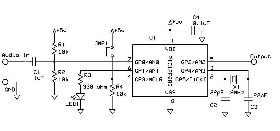
DTMF Touch Tone Decoder Using Microchip PIC Microprocessor. This project contains the details of using a Microchip PIC12F683 8-bit microprocessor to detect Dual-Tone Multi-Frequency (DTMF) signals. The DTMF Touch Tone Decoder circuit utilizes the Microchip PIC12F683 microprocessor, which is an...
The subwoofer is a speaker designed to reproduce low frequencies, specifically in the range of 20 Hz to 150 Hz. The electronic circuit diagram below illustrates the details of a subwoofer amplifier using the TDA1516, a 22-watt amplifier suitable...

This varactorless high-frequency modulator electronic project must be powered by a simple DC 3-volt power source, such as a 3-volt battery. Traditionally, high-frequency oscillators are frequency-modulated using a varactor. However, varactors typically require a significant voltage change to achieve...

A PC-based data logger utilized in physics laboratories for automating simple experiments and monitoring slowly varying physical variables across various PC-based projects. The PC-based data logger serves as an essential tool in physics laboratories, enabling the automation of experiments and...
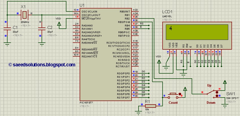
This tutorial on the PIC16F877 microcontroller addresses the implementation of an up-down counter using the PIC16F877. The process utilizes the PIC16 simulator (Proteus). The PIC16F877 microcontroller is a versatile device commonly used in various applications, including counter circuits. An up-down...
Warning: include(partials/cookie-banner.php): Failed to open stream: Permission denied in /var/www/html/nextgr/view-circuit.php on line 713
Warning: include(): Failed opening 'partials/cookie-banner.php' for inclusion (include_path='.:/usr/share/php') in /var/www/html/nextgr/view-circuit.php on line 713