
MicroSimon
This project demonstrates the creation of a Simon game clone using an 8-pin PIC12F683 microcontroller. It features a complete emulation of the original Simon game and allows players to select from four skill levels, which dictate the number of colors to repeat in a sequence to win. The project was developed for Sparkfun's microcontroller competition in 2011 and showcases various design techniques applicable to low-pin count microcontrollers. The code is written entirely in C and fits within the 2K program flash available on the chip. The PCB measures only 1.5 inches square and incorporates both SMD and through-hole components, though it can also be reproduced using larger components on a breadboard or small strip-board. Power is supplied by a standard CR2032 3V lithium cell mounted on the underside of the game. The design utilizes the ultra-low power standby feature of the microcontroller, eliminating the need for a power switch. Overall power consumption is minimized by using the internal oscillator of the PIC running at 4MHz. The board is a small dual-layer PCB, with all components mounted on the top side except for the battery holder, which is on the bottom to save space. The in-circuit programming header is optional and can be omitted for a neater appearance. The PCB was fabricated using the UV photo-resist technique, ensuring good track accuracy suitable for hobbyist setups. The hardware design employs a common microcontroller technique, utilizing a single ADC (Analog to Digital Converter) pin to connect four color buttons. Each switch connects to the controller through a pull-down resistor to ground, forming the lower half of a voltage divider. The upper half is created with a network of 10K resistors connected to the push-buttons. Depending on the button pressed, either 0 Ohms, 10K Ohms, 20K Ohms, or 30K Ohms is connected to the voltage divider's top half. The software polls the ADC and reads a 10-bit conversion value for the pin (ranging from 0 to 1023, with 0 being Vss and 1023 being Vdd). Each button is assigned a specific range of values to account for resistor tolerances. This design advantageously uses Vdd (3 volts) as the reference for conversion, maintaining accuracy even as the battery voltage decreases. Instead of a bulky toggle switch for power control, the hardware employs the low-power sleep mode of the PIC. The game starts when the MCLR reset button is pressed, and once the game ends, the PIC enters low-power sleep mode. The PIC's low power drain in sleep mode allows for prolonged battery life. The LEDs are connected to the PIC using three pins through charlieplexing, which leverages the diode behavior of LEDs to control power flow direction. The PIC’s IO pins can be in one of three states: 0V (sinking power to ground), 3V (sourcing power from Vdd), or in high-impedance mode (effectively disconnected). This setup enables control of up to six LEDs using only three pins, although the game only requires four.
The schematic design of the Simon game clone integrates several key components and techniques that optimize both functionality and efficiency. The microcontroller, PIC12F683, serves as the central processing unit, executing the game logic and managing input and output operations. The ADC pin connected to the color buttons allows for a simple yet effective method of detecting user input through voltage division. Each button, when pressed, alters the voltage seen at the ADC pin, providing distinct values that the software interprets to determine which button was activated.
The PCB layout is compact, designed to maximize space while ensuring ease of use. The choice of using both SMD and through-hole components reflects a balance between compactness and accessibility for hobbyists. The CR2032 battery provides a reliable power source, and its placement on the underside of the board is a thoughtful choice that contributes to the overall compact design.
Power management is a crucial aspect of this design. By utilizing the low-power sleep mode of the PIC, the game conserves battery life, which is particularly important in portable applications. The absence of a traditional power switch simplifies the user experience, allowing for immediate gameplay upon pressing the reset button.
The charlieplexing technique employed for LED control is an efficient use of the available pins, allowing for a greater number of outputs than would typically be possible with direct pin assignments. This method not only saves space on the PCB but also reduces the complexity of the circuit.
In summary, this Simon game clone project serves as an exemplary model of efficient microcontroller design, showcasing effective use of components, innovative input methods, and robust power management strategies, making it a valuable reference for similar projects in the field of electronics.This project shows how to create an MB Electronics Simon game clone using an 8-pin PIC12F683 microcontroller. The game includes a full emulation of the original Simon `game 1` and the ability to select from 4 skill levels which control the number of colours you must repeat in a sequence in order to win the game.
The project was created for Sparkfu n`s microcontroller competition 2011 and aims to demonstrate a number of useful design techniques which can be used when working with low-pin count microcontrollers. The code is written entirely in C and fits neatly into the 2K of available program flash on the chip.
The PCB is only 1. 5 inches square and uses both SMD and through-hole components, however it is perfectly possible to recreate the project using larger components on a breadboard or a small piece of strip-board. The game is powered by a stanard CR2032 3V lithium cell which is mounted on the underside of the game.
The design uses the ultra low power standby feature of the microcontroller meaning that no power switch is required. Overall power consumption is kept to a minimum by using the internal oscillator of the PIC running at 4Mhz.
The board is a small dual-layer PCB, all components are mounted top-side apart from the battery holder which is mounted on the bottom of the board to save space. I tried to make the board as small as possible whilst still being playable (I have big thumbs!). The in-circuit programming header can be omitted if not required to make the hardware neater looking.
The PCB was made using the UV photo-resist technique which allows for good track accuracy even from a hobbyist set up. Here is a picture of the board created in Eagle: The hardware design uses a common microcontroller trick of using a single ADC (Analogue to Digital Converter) pin to connect the 4 colour buttons of the game.
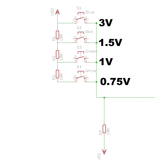
Each switch is connected to the controller through a single `pull-down` resistor to earth which acts as the lower half of the voltage divider. The other half of the voltage divider is created using a network of 10K resistors on the other side of the push-buttons.
Depending on what button you press you connect either 0 Ohms, 10K Ohms, 20K Ohms or 30K Ohms to the top half of the voltage divider. Using some simple ohms-law maths you can then work out the voltage for any given switch as shown in the following diagram: The software simply polls the ADC converter and reads a 10-bit conversion value for the pin (0-1023 with 0 being Vss and 1023 being Vdd).
Each button is allocated a small range of possible values to allow for variance in the values of the resistors. The nice thing about this design is that the processor uses Vdd (3 volts) as the reference for the conversion so even as the battery drains it is still accurate since the input voltage to the divider and the PIC`s Vref is the same.
Instead of using a bulky toggle switch for the power control the hardware uses the low-power sleep mode available on the PIC. The `start` button for the game is actually a MCLR reset button. When the PIC is reset the game starts, once the game is over the PIC enters low-power sleep. Pressing the reset button resets the controller and the game starts again. The power drain of the PIC in sleep mode is very low so it would take some considerable time for it to deplete the 3V battery.
The LEDs are connected to the PIC using 3 pins. This is achieved by using `charlieplexing` which takes advantage of the fact that an LED is a diode and only allows power to flow in one direction. The PIC`s IO pins are `tri-state` meaning they can be 0V (sinking power to ground), 3V (sourcing power from Vdd) or `high-impedance` inputs (high impedance is a fancy expression meaning that the pin is effectively disconnected and virtually no power flows through it).
Using 3 pins it is possible to control up to 6 LEDs, however the game only requires 4 as shown in the following diagram: The sound circuit 🔗 External reference
The schematic design of the Simon game clone integrates several key components and techniques that optimize both functionality and efficiency. The microcontroller, PIC12F683, serves as the central processing unit, executing the game logic and managing input and output operations. The ADC pin connected to the color buttons allows for a simple yet effective method of detecting user input through voltage division. Each button, when pressed, alters the voltage seen at the ADC pin, providing distinct values that the software interprets to determine which button was activated.
The PCB layout is compact, designed to maximize space while ensuring ease of use. The choice of using both SMD and through-hole components reflects a balance between compactness and accessibility for hobbyists. The CR2032 battery provides a reliable power source, and its placement on the underside of the board is a thoughtful choice that contributes to the overall compact design.
Power management is a crucial aspect of this design. By utilizing the low-power sleep mode of the PIC, the game conserves battery life, which is particularly important in portable applications. The absence of a traditional power switch simplifies the user experience, allowing for immediate gameplay upon pressing the reset button.
The charlieplexing technique employed for LED control is an efficient use of the available pins, allowing for a greater number of outputs than would typically be possible with direct pin assignments. This method not only saves space on the PCB but also reduces the complexity of the circuit.
In summary, this Simon game clone project serves as an exemplary model of efficient microcontroller design, showcasing effective use of components, innovative input methods, and robust power management strategies, making it a valuable reference for similar projects in the field of electronics.This project shows how to create an MB Electronics Simon game clone using an 8-pin PIC12F683 microcontroller. The game includes a full emulation of the original Simon `game 1` and the ability to select from 4 skill levels which control the number of colours you must repeat in a sequence in order to win the game.
The project was created for Sparkfu n`s microcontroller competition 2011 and aims to demonstrate a number of useful design techniques which can be used when working with low-pin count microcontrollers. The code is written entirely in C and fits neatly into the 2K of available program flash on the chip.
The PCB is only 1. 5 inches square and uses both SMD and through-hole components, however it is perfectly possible to recreate the project using larger components on a breadboard or a small piece of strip-board. The game is powered by a stanard CR2032 3V lithium cell which is mounted on the underside of the game.
The design uses the ultra low power standby feature of the microcontroller meaning that no power switch is required. Overall power consumption is kept to a minimum by using the internal oscillator of the PIC running at 4Mhz.
The board is a small dual-layer PCB, all components are mounted top-side apart from the battery holder which is mounted on the bottom of the board to save space. I tried to make the board as small as possible whilst still being playable (I have big thumbs!). The in-circuit programming header can be omitted if not required to make the hardware neater looking.
The PCB was made using the UV photo-resist technique which allows for good track accuracy even from a hobbyist set up. Here is a picture of the board created in Eagle: The hardware design uses a common microcontroller trick of using a single ADC (Analogue to Digital Converter) pin to connect the 4 colour buttons of the game.
Each switch is connected to the controller through a single `pull-down` resistor to earth which acts as the lower half of the voltage divider. The other half of the voltage divider is created using a network of 10K resistors on the other side of the push-buttons.
Depending on what button you press you connect either 0 Ohms, 10K Ohms, 20K Ohms or 30K Ohms to the top half of the voltage divider. Using some simple ohms-law maths you can then work out the voltage for any given switch as shown in the following diagram: The software simply polls the ADC converter and reads a 10-bit conversion value for the pin (0-1023 with 0 being Vss and 1023 being Vdd).
Each button is allocated a small range of possible values to allow for variance in the values of the resistors. The nice thing about this design is that the processor uses Vdd (3 volts) as the reference for the conversion so even as the battery drains it is still accurate since the input voltage to the divider and the PIC`s Vref is the same.
Instead of using a bulky toggle switch for the power control the hardware uses the low-power sleep mode available on the PIC. The `start` button for the game is actually a MCLR reset button. When the PIC is reset the game starts, once the game is over the PIC enters low-power sleep. Pressing the reset button resets the controller and the game starts again. The power drain of the PIC in sleep mode is very low so it would take some considerable time for it to deplete the 3V battery.
The LEDs are connected to the PIC using 3 pins. This is achieved by using `charlieplexing` which takes advantage of the fact that an LED is a diode and only allows power to flow in one direction. The PIC`s IO pins are `tri-state` meaning they can be 0V (sinking power to ground), 3V (sourcing power from Vdd) or `high-impedance` inputs (high impedance is a fancy expression meaning that the pin is effectively disconnected and virtually no power flows through it).
Using 3 pins it is possible to control up to 6 LEDs, however the game only requires 4 as shown in the following diagram: The sound circuit 🔗 External reference