
Millimeter-Wave CMOS Impulse Radio
The edge combiner design integrates MOSFETs C and D, which are critical for pulse generation with a target of 16 ps. The performance of the edge combiner is highly dependent on the NMOS width (Wser) in relation to the inverter width (Winv), as this relationship influences the center frequency of the generated pulses. The analysis of signal behavior in the modulator, illustrated in Figure 12, is essential for understanding the dynamics of transmitted, reflected, dissipated, and leaked signals during operation. The impedance transformation along the modulator, shown in Figure 13, is significant for optimizing the performance of the device, ensuring minimal signal loss and effective power transfer.
Transient simulations, as depicted in Figure 16, provide insight into the response characteristics of the NMOSFET switch, which is vital for evaluating the timing and integrity of the generated signals. The architecture of the millimeter-wave pulse transmitter, whether single-ended or differential-ended, plays a crucial role in defining the operational efficiency and spectral characteristics of the system. Measurement data in Figure 27 highlights the correlation between the oscillator's operating frequency, power dissipation, and output power, offering valuable metrics for performance assessment in practical applications.
Millimeter waves, characterized by their short wavelengths, present unique challenges and opportunities for wireless communication. The historical context of their discovery and the implications of oxygen absorption at 60 GHz underline the importance of material properties and environmental factors in system design. The advancements in CMOS technology have paved the way for innovative circuit designs that leverage the benefits of millimeter-wave frequencies, particularly in terms of bandwidth availability and communication speed. The reduction of power consumption remains a critical focus area, particularly for components such as local oscillators and converters, which traditionally consume significant power in transceiver architectures. The presented low-power pulse transmitter circuits exemplify the ongoing efforts to optimize performance while addressing power efficiency, thereby enhancing the feasibility of millimeter-wave applications in consumer electronics.An edge combiner comprising MOSFETs C and D has to generate a 16ps pulse. Centre frequency as a function of NMOS width Wser over inverter width Winv. Figure 12. Illustration of transmitted, reflected, dissipated and leaked signals of a switch in the (a) ON and (b) OFF states of the modulator when the millimeter-wave signal travels from source to the load. Figure 13. a) Impedance transformation along the modulator and (b) calculated reflected, dissipated and leaked powers as a function of the transmission line distance between switches. Figure 16. Transient simulation; (a) 200ps applied data pulse, and responses of (b) the gate voltage of the NMOSFET switch, and (c) input and (d) output signals.
Figure 22. Architecture of (a) a single-ended millimeter-wave pulse transmitter with off-chip 60GHz CW source and (b) a proposed differential-ended pulse transmitter with on-chip 60GHz CW source. Figure 27. Measured (a) operating frequency of the oscillator and (b) power dissipation and output millimeter-wave power of the oscillator as a function of supply voltage.
Millimeter waves are electromagnetic waves with wavelengths of 1 to 10 mm in vacuum, and they were discovered experimentally in the 19th century ( Wiltse, 1984 ). In 1946, the most unique feature of millimeter waves, oxygen absorption at 60 GHz, was reported, which results in the rapid attenuation of electromagnetic waves in the air ( Beringer, 1946 ).
Although the oxygen absorption makes long-distance wireless communication difficult, it enables us to allocate a wide frequency band, which realizes ultra-high-speed communication greater than 1Gbps (gigabits-per-second). Recently, the well-known feature of millimeter-wave communication has attracted attention again because millimeter-wave circuits have been realized with advanced CMOS technologies, and the recent 60GHz band license-free regulations with license-free bandwidths of 9GHz in Europe and 7GHz in Japan, USA, Canada and Korea.
In academic conferences and journals, many studies on millimeter-wave CMOS circuits were reported in the past few years, and consumer devices are expected to be available soon. Here, for realizing the consumer application of millimeter waves, the reduction of power consumption is the most important issue.
It is noted that the power-hungry building blocks in a transceiver are the local oscillator (LO) based on the phase-locked loop (PLL), and analog-to-digital and digital-to-analog converters (ADC and DAC) as shown in Figure 1 (a) ( Marcu, 2009 ). If these blocks can be eliminated partially or completely in a transceiver, power consumption will be considerably reduced.
From this viewpoint, we have studied millimeter-wave pulse communication for high-performance CMOS wireless transceivers as shown in Figure 1 (b) and Figure 1 (c). In this study, low-power direct pulse generators, high-speed switches and receivers, which are the most important building blocks in millimeter-wave pulse communication, are discussed for high-speed wireless communications using the 60 GHz band.
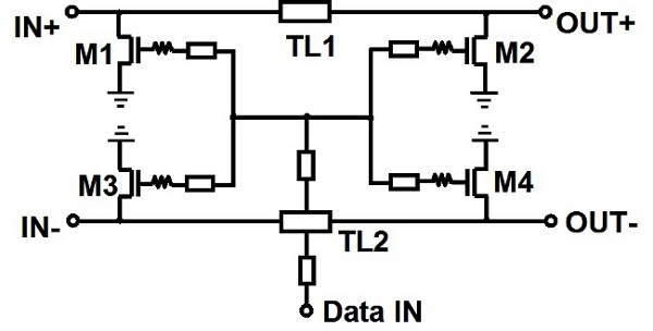
In conclusion, the prospects for millimeter-wave pulse communication will be addressed. In this section, three low-power 60GHz CMOS pulse transmitter circuits are presented. The first one is a carrier-less direct pulse generator circuit, ( Badalawa, 2007 ). The second design presents an 8Gbps millimeter-wave CMOS switch used for an Amplitude Shift Keying (ASK) modulator ( Oncu, 2008, and the last one presents a design of a low-power 10Gbps Block diagram of wireless communication based on (a) carrier modulation, (b) direct pulse generator without oscillator, (c) pulse generator with millimeter-wave oscillator. CMOS transmitter for a 60GHz millimeter-wave impulse radio, where a 60GHz millimeter-wave continues-wave (CW) source and ASK modulator circuits are embedded on the same silicon substrate.
The circuit topology of the proposed pulse generator (PG) 🔗 External reference
Related Circuits
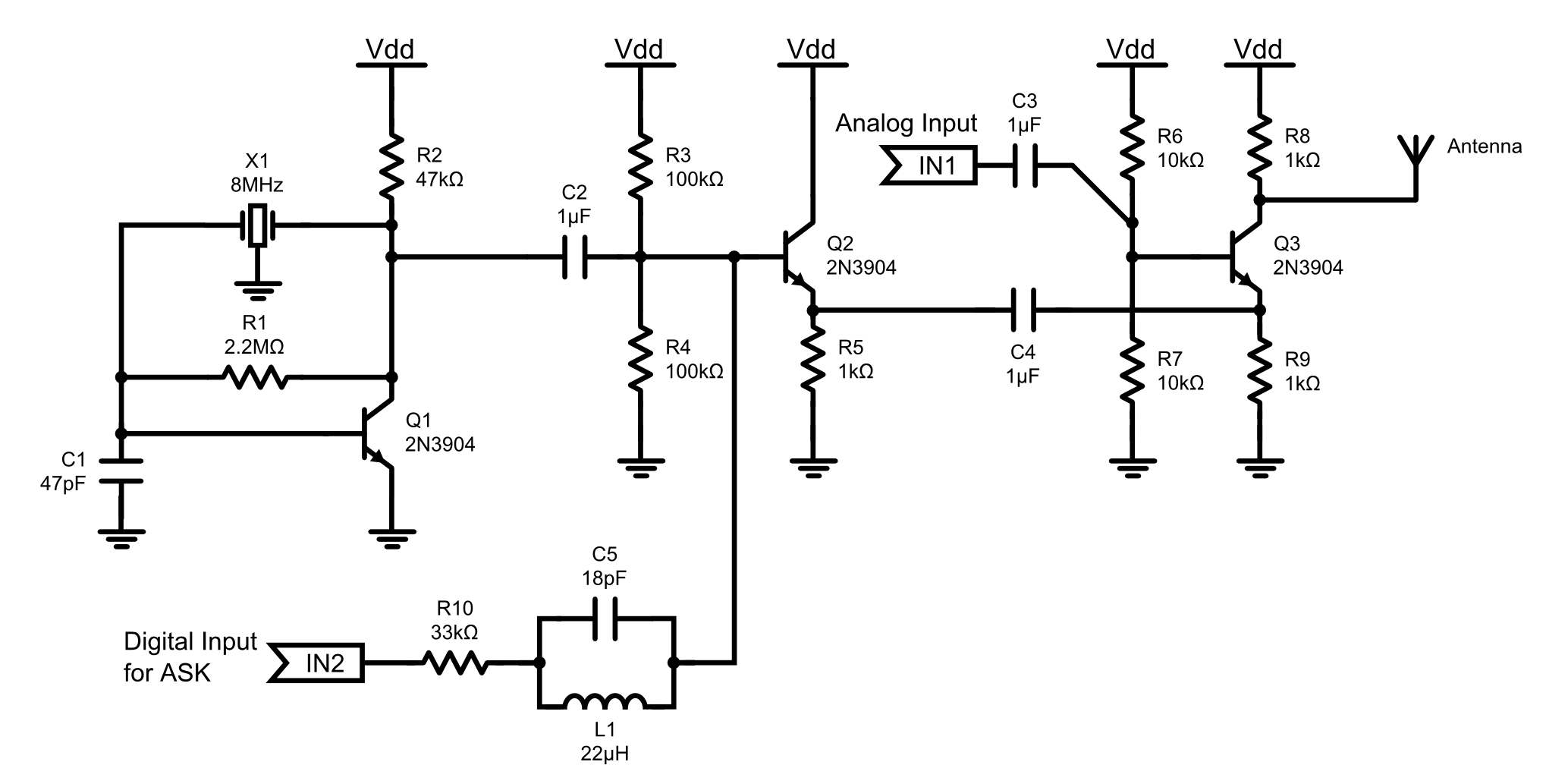
This is an 8MHz amplitude modulated (AM) radio transmitter designed primarily for work purposes and as an exercise in electronics. It serves as a simple radio transceiver that may be utilized for various future projects. The 8MHz AM radio transmitter...
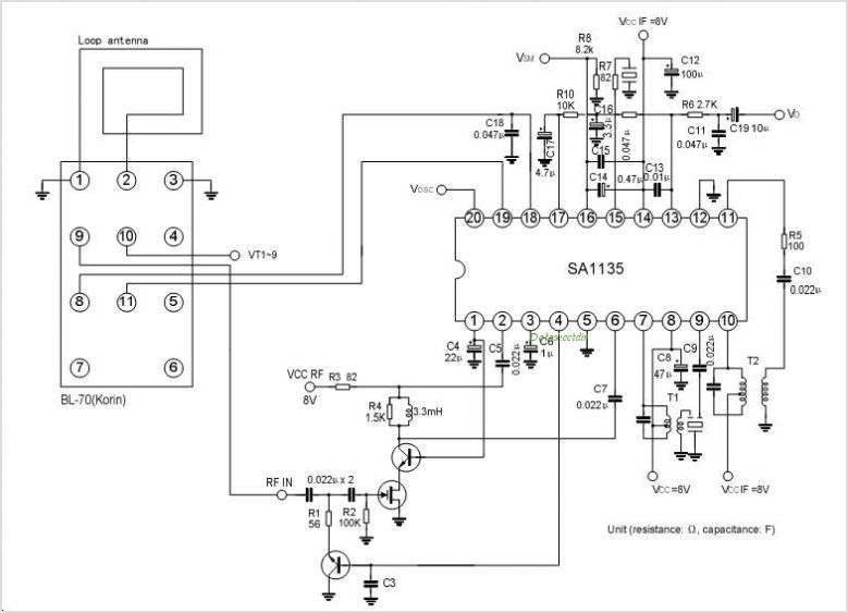
The SA1140 is an intermediate frequency (IF) system integrated circuit (IC) tailored for FM car stereo receivers. It offers adaptable muting characteristics that can be modified using external components. Manufactured by Silan. The SA1140 is engineered to enhance the functionality...
A regenerative radio operates by feeding back a small portion of the amplified output from the detector into the input. This feedback mechanism enhances sensitivity significantly beyond what a detector can achieve on its own. The simple regenerative radio...
This AM radio receiver circuit utilizes the TDA1083 radio IC, which is suitable for constructing a simple medium frequency (MF) band radio. The schematic operates within a frequency range of 300 kHz to 3 MHz. The circuit is straightforward...
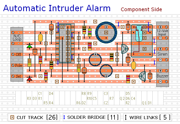
This circuit includes automatic exit and entry delays, a timed bell cut-off, and a system reset feature. It is designed to work with standard normally-closed input devices such as magnetic reed contacts, micro switches, foil tape, and passive infrared...
This CMOS square-wave oscillator utilizes the 4047 multivibrator circuit, suitable for both monostable (one-shot) and astable applications. In the provided configuration, the 4047 operates as an astable multivibrator. The circuit features three outputs from the 4047, with the first...
Warning: include(partials/cookie-banner.php): Failed to open stream: Permission denied in /var/www/html/nextgr/view-circuit.php on line 713
Warning: include(): Failed opening 'partials/cookie-banner.php' for inclusion (include_path='.:/usr/share/php') in /var/www/html/nextgr/view-circuit.php on line 713