
Mini DDS circuit
The function generator circuit is designed to provide a versatile and efficient means of generating various waveforms for testing and experimentation. The AT2313 microcontroller plays a crucial role in the functionality of the device, executing the programmed logic to control the output waveform characteristics. The R2R resistor network, which acts as the DAC, converts the digital output from the microcontroller into an analog voltage. The network’s design allows for a straightforward implementation while achieving adequate performance for most applications.
The voltage regulator, specifically the MAX603, is essential for maintaining a stable operating voltage for the entire circuit, ensuring reliable performance across varying conditions. The RS232 interface allows for easy communication between the PC and the function generator, enabling users to set parameters such as frequency and waveform type through the Windows application. The choice of using RS232 facilitates compatibility with a wide range of devices, making the function generator accessible for various applications.
The output stage of the function generator may require additional buffering to mitigate the effects of high output impedance, which can lead to signal distortion or loading issues when connected to other circuits. This can be achieved by incorporating an operational amplifier configured as a voltage follower, which would provide a low output impedance while preserving the signal integrity.
Overall, this simple function generator exemplifies an efficient design that leverages readily available components, providing a practical solution for generating a variety of waveforms in a compact and cost-effective package. The system's modular design allows for potential upgrades and modifications, such as the integration of the AD9832 chip in the future, which could enhance the functionality and performance of the generator.A simple function generator. Just to generate a certain frequency. While waiting for the AD9832 chip to arrive, I came up with a very simple version of the DDS synth, using just the 2313 and a resistor network. It`s controlled over RS232 from a small Windows program, and can generate Sine-, Sawtooth-, Trangle- and Sqare-waves ranging from 0.
07 Hz to about 200-300 kHz in 0. 07 Hz steps (depending on your crystal). I wont go into details about how a DDS synth works. Maybe later. The code is pretty simple so you should be able to understand how it works by just reading through it. There`s not much to say about the schematic. It`s as simple as can be. Just 4 major parts. A voltage regulator/switch, a RS232 interface chip, the 2313 and the R2R resistor network. The R2R network is connected to PORTB on the 2313, making it a simple D/A converter and makes it possible to output 256 voltage levels.
Neither the resistor network or port drivers of the 2313 is of perfect linearity, but it works pretty well anyway. But you`ll probably need a buffer stage as the output impedance is rather high (tens of kOhms in my case).
The MAX603 handles the voltage regulation as well as the powerup/shutdown function, and is controlled by the DTR signal on the serial interface. So when you shut down the control program on the PC, the miniDDS will be shutdown, saving battery. The phase accumulator uses 24 bits, which determines the resolution of the output frequency. Maximum available frequency and resolution is also dependent on your crystal frequency : 🔗 External reference
Related Circuits
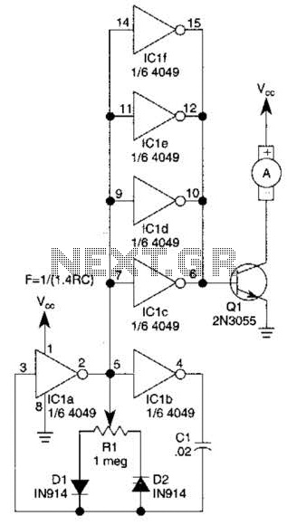
This circuit will drive a small DC motor over a wide range of speeds without stalling by controlling the duty cycle of the motor, rather than the supply voltage. The described circuit utilizes pulse width modulation (PWM) to effectively control...
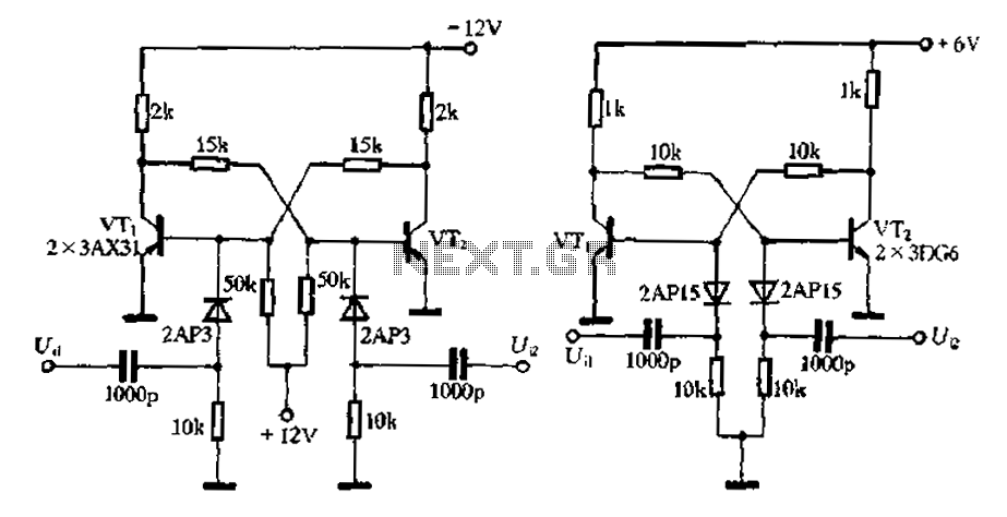
Bistable circuit operating at a frequency of 10 kHz or lower. A bistable circuit, also known as a flip-flop, is a fundamental building block in digital electronics. It has two stable states and can store one bit of data. The...
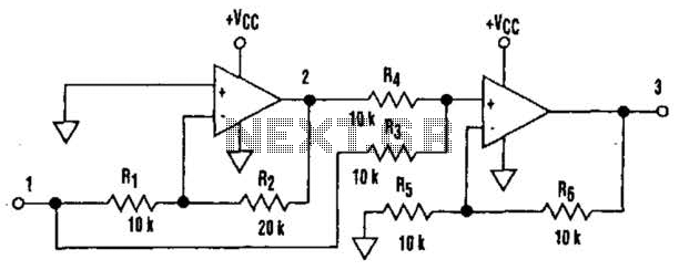
It is well understood that utilizing single-supply operational amplifiers (op amps) can present challenges when implementing simple functions in a bipolar signal environment. Often, this necessitates the use of additional op amps and other electronic components. Considering this, it...
All car batteries require a 12V battery charger, which also applies to marine, RV, and power sports batteries. The high-efficiency lead-acid batteries available today necessitate more effective charging techniques. The battery charger is a crucial tool for prolonging battery...
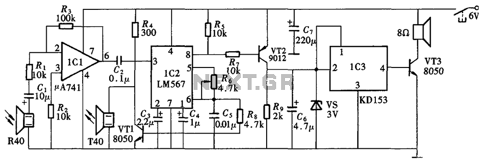
The Blind Pathfinder circuit primarily consists of the A741 operational amplifier, LM567 phase-locked loop, KD153 transistor, 8050 transistor, 9012 transistor, and various other components. The Blind Pathfinder circuit is designed to assist in navigation and obstacle detection, typically utilized in...
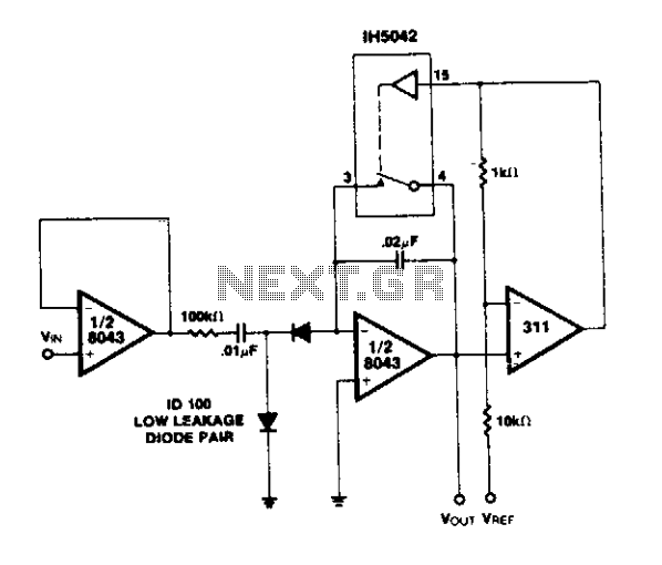
A simple circuit utilizing an LM311 as a level detector and a CMOS analog gate for capacitor discharge is presented. A notable feature of this counter type is the ease of changing the count, which only requires adjusting the...
Warning: include(partials/cookie-banner.php): Failed to open stream: Permission denied in /var/www/html/nextgr/view-circuit.php on line 713
Warning: include(): Failed opening 'partials/cookie-banner.php' for inclusion (include_path='.:/usr/share/php') in /var/www/html/nextgr/view-circuit.php on line 713