
Mini Organ using timer 555

The described circuit functions as an astable multivibrator, which is a type of oscillator that continuously switches between its high and low states without requiring any external triggering. The circuit utilizes an NE555 timer integrated circuit (IC1) configured in an astable mode, generating square wave output signals.
The operation of the circuit begins with the selection of an octave using switch S9. This switch allows the user to choose between different frequency ranges, effectively altering the pitch of the generated tones. The tones themselves are determined by the variable resistors P1 through P8, which are 100kΩ spindle trimmers. Each of these trimmers adjusts the resistance in the timing circuit of the NE555, thereby changing the frequency of the output waveform, which corresponds to musical notes.
Pressing the buttons S1 to S8, which are normally open (NO) contacts, enables the user to select specific notes. When a button is pressed, it activates the corresponding tone, and if two buttons are pressed simultaneously, the circuit produces a combination tone. This feature allows for chord generation, enhancing the musical capabilities of the circuit.
The output from the NE555 timer is taken from the 'out' point, which can be connected to an amplifier. This amplifier will boost the signal to a level suitable for driving speakers or other audio output devices, allowing the generated tones to be heard clearly.
The circuit components include resistors and capacitors that define the timing characteristics of the NE555. For instance, R1 is a 10kΩ resistor, while capacitors C1, C2, C3, and C4 are used to set the timing intervals for the oscillation. C1 and C4 are 100nF capacitors, C2 is a 150nF capacitor, and C3 is a 10nF capacitor. The selection of these component values determines the frequency range and stability of the oscillation, which is critical for producing musical tones accurately.
In summary, this astable multivibrator circuit with octave selection and tone generation capability provides a versatile platform for sound synthesis, suitable for various electronic music applications.This circuit operates as a astabiele multivibrator. With switch S9 can 'octave' chosen. The tones are set by P1 to P8. Pressing S1 to S8 displays the corresponding note, pressing two buttons at the same time gives it a tone. At the point 'out' can be connected to an amplifier show display. Parts List R1 = 10k? P1 .. P8 = 100k? (spindle trimmers) C1 = 100nF C2 = 150nF C3 = 10nF C4 = 100nF IC1 = NE555 S1 .. S8 = NO contact S9 = way switch 🔗 External reference
Related Circuits
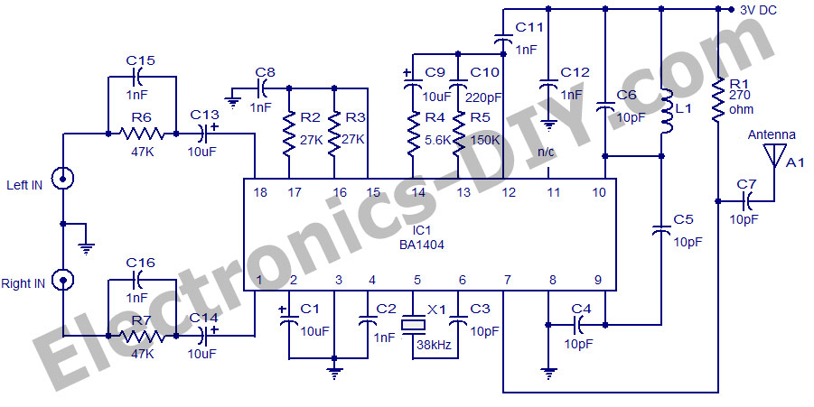
A high-quality stereo FM transmitter circuit is presented here. The circuit utilizes the IC BA1404 from ROHM Semiconductors. The BA1404 is a monolithic FM stereo modulator that incorporates a built-in stereo modulator, FM modulator, and RF amplifier circuitry. The...
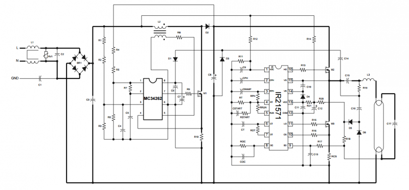
The circuit is built around the IR2520D Ballast Control IC. The IR2520D provides adjustable preheat time, adjustable run frequency to set the lamp power, high starting frequency for soft start and to avoid lamp flash, fault protection for open...
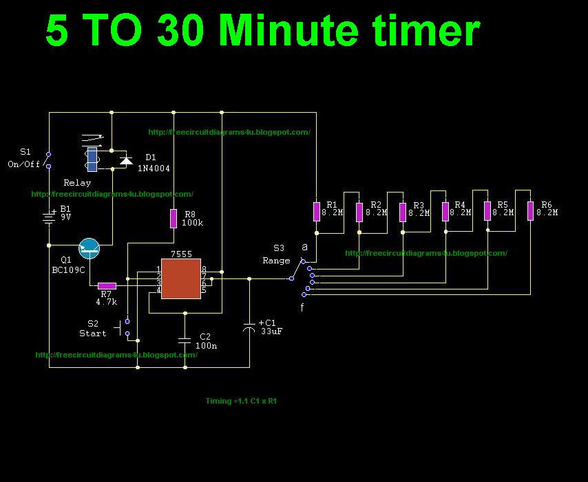
This circuit illustrates the use of the 7555 integrated circuit (IC) for a timer circuit that can be set to operate between 5 to 30 minutes. This circuit is beneficial as it allows for timed operations. The 7555 timer IC...
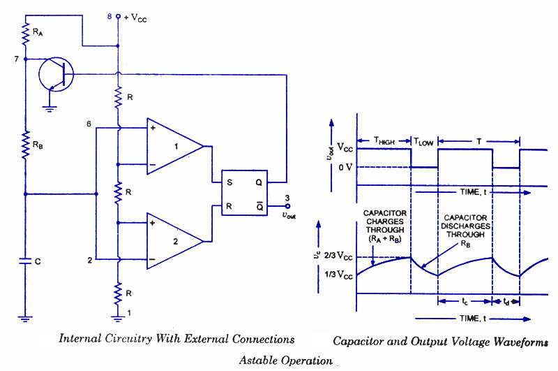
An astable multivibrator, often referred to as a free-running multivibrator, is a rectangular-wave generating circuit. Unlike the monostable multivibrator, this circuit does not require any external trigger to change the state of the output, hence the term free-running. Before...
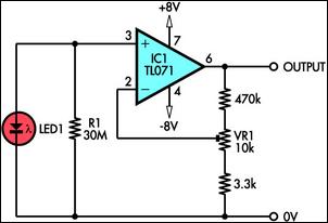
This circuit demonstrates the use of a standard LED as a light sensor by utilizing the photovoltaic voltage generated across the LED when it is exposed to light. LEDs are cost-effective alternatives to photodiodes and include a built-in filter...
This circuit, based on the 555 timer, functions as a voltmeter and an analog-to-digital converter, converting analog input voltage into digital output pulses. The 555 timer is a versatile integrated circuit commonly used for timing, oscillation, and pulse generation applications....
Warning: include(partials/cookie-banner.php): Failed to open stream: Permission denied in /var/www/html/nextgr/view-circuit.php on line 713
Warning: include(): Failed opening 'partials/cookie-banner.php' for inclusion (include_path='.:/usr/share/php') in /var/www/html/nextgr/view-circuit.php on line 713