
Mini strobe light
The circuit utilizes the NE555 timer IC configured in astable mode, functioning as a self-oscillator to generate a square wave output. The frequency of oscillation is determined by the values of the timing resistor and capacitor connected to the NE555. A variable resistor (VR) is included in the circuit to allow for the adjustment of the pulse width, thereby changing the frequency of the output signal. The output frequency can range from 40 Hz to 166 Hz, depending on the resistance value set on the variable resistor.
An LED is connected to the output of the NE555, which causes it to blink in synchronization with the oscillating frequency, creating a strobe light effect. This strobe light can be used in various applications, including visual demonstrations of sound waves and vibrations. The circuit also includes a speaker, which is driven by a 3V AC power transformer. The speaker cone vibrates at a frequency of 50 Hz, and by adjusting the variable resistor, the oscillation can be fine-tuned to 51 Hz. This allows for the observation of the speaker cone's slow vibrations at a 1 Hz rate when viewed under strobe lighting conditions.
In educational settings, this circuit serves as an effective tool for teaching concepts of sound, vibration, phase, and frequency. It can also be employed in practical applications to evaluate the mechanical stability of components on a printed circuit board (PCB). The simplicity and low cost of the design make it accessible for various learning and experimental purposes.This is a mini strobe light. NE555 is used as a self oscillator. The width of output pulse is changed by the variable resister. 25msec means 40Hz. 6m sec means 166Hz. A LED is connected on the output of this oscillator. Therefore LED twinkles from 40Hz to 166Hz. I lighted a speaker by this twinkle LED. The cone of a speaker is vibrated by 50Hz with 3V-AC power transformer. I adjusted the VR to oscillate 51Hz. Then, I can watch the corn of the speaker vibrates slowly with 1Hz. A strobe scope is used in order to research the vibration. This is very cheap one. If you are the teacher, you can teach the children that the sound is a vibration of the air. Also you can teach that the concept of phase and frequency with this equipment with this machine. If you are the young man, you can have a time with your girl friend in the dark room.( Last month I looked this light with 5 gentlemen. It was not enjoyable time HIHI) Description add on 10 Dec 2000: I forget to say about most important thing.
Such a instrument can be uaed to evaluate the mechanical stability of the parts on the print boad. 🔗 External reference
Related Circuits
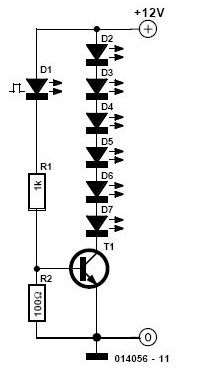
This simple and inexpensive circuit is not limited to Christmas. It consists of two resistors, a small-signal transistor such as a BC547, one flashing LED, and a string of standard LEDs. The flashing LED functions as an oscillator, turning...
A 1200 Watt lamp dimmer circuit is designed to control lighting levels and is capable of managing up to 1200 Watts. This circuit utilizes the Q4015LT, which combines a Diac and a Triac for 230V dimming applications. It serves...
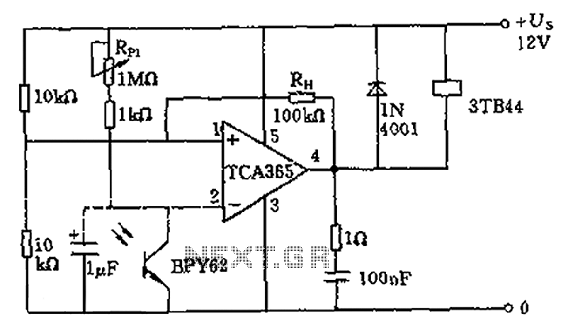
A bridge input circuit utilizing a phototransistor BPY62 and a power operational amplifier is capable of controlling power loads up to 8.5 kW. It features a voltage divider composed of two 10 kΩ resistors, creating a midpoint connection. The...
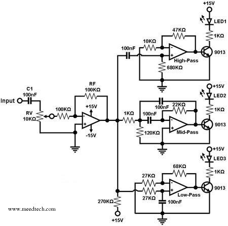
A simple circuit for converting an audio signal (such as one that comes from the output terminals of a CD player). The circuit basically consists of a buffer/amplifier stage and three filter circuits: a high-pass filter, a mid-pass filter,...
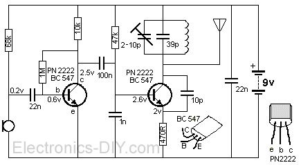
The FM transmitter is a simple and compact device with a transmission range of 100-150 meters, offering good sensitivity and low current consumption. The schematic of the transmitter includes a bass amplifier for the first transistor and a frequency...
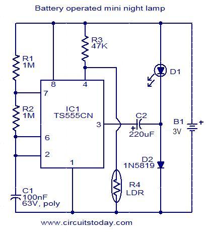
This circuit is designed as a low-power LED night lamp that automatically switches off during daytime. The CMOS timer IC TS555CN is configured as a square wave generator operating at approximately 5 Hz. The output voltage from the IC...