
MiniVol PGA2320 Volume Control
der as the user interface. The microcontroller`s EEPROM is used to store the current setting between power cycles. Since the PGA2320 offers up to 31. 5dB of gain, a jumper is provided to limit the control to 0dB. No additional functionality is provided, honouring the KISS principle. An external ±15V power supply is required, such as my MiniPow. A dual-layer PCB design and firmware are available and free for DIY use. The PCB was designed to be small and modular, perfectly suited to a DIY amp or preamp project as an inexpensive and excellent-sounding alternative to a potentiometer or stepped attenuator. With two boards it can be used for a balanced configuration fairly easily (see build notes for details).
SMD components are used almost exclusively, since the PGA2320 is available only in the SO-16 pacakage, and because size was a major design parameter. Parts cost without the PCB is about $25. If there is sufficient demand, I might consider offering boards and preprogrammed microcontrollers for sale.
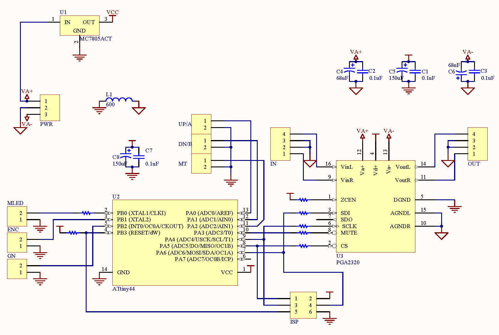
MiniVol requires at a minimum a ±15V regulated supply, which is further regulated by an onboard 78L05 to 5V for the digital control section. An external 5V supply could be used if desired, by tapping ground and Vcc at the U1 position. Onboard decoupling consists of 150 µF electrolytic in parallel with 100nF X7R ceramic for each chip on the digital supply, and 68 µF electrolyic in parallel with 100nF X7R ceramic for the ± analog supplies.
This decoupled supply feeds the PGA2320, which has the source signal connected directly to its inputs. No buffering is provided onboard, though the PGA2320 should be driven by a source with 600 © or lower output impedance.
An Atmel ATtiny24/44/84 provides digital control to the system, through six user interface pins. For input, two pins are exposed to provide for either UP/DOWN pushbutton input or a rotary encoder and a third pin provides for a mute button. Two `jumper` inputs are provided as well: ENC selects whether an encoder or pushbuttons are in use, GN selects whether the PGA2320 should be capped at 0dB gain.
All inputs utilise the AVR`s internal pull-ups. MLED provides an output to drive a mute LED when the system is muted. An ISP connector is connected directly to the AVR`s SPI port to facilitate programming. The SPI port is also connected to the PGA2320 through 10K © resistors. In the image, blue areas are copper in the bottom layer, red areas are copper in the top layer, purple areas have copper in both layers, white areas are the top layer silkscreen. The main goal of the PCB layout was to separate the digital and analog sections as much as possible, and to keep both types of signals` current loops as small as possible.
I believe both of these goals were achieved. Two unbroken ground planes are used per the PGA2320 datasheet, and connected at a single point with a ferrite chip; this point is directly below the 5V regulator`s feed trace from V+ to keep the loop small and out of the way of the analog section. Signal-carrying traces are short and kept away from any digital signals - despite the fact that the microcontroller will be in sleep mode almost all the time.
Two mounting holes are provided. The table below lists parts for the MiniVol. Substitutions may be made at the builder`s discretion; most values and part numbers are not critical. Detailed descriptions and substitutes are below the table. The firmware is a rather over-the-top design. I am intending to use this basic model as a basis for several much larger projects, so I figured I may as well start here.
It is largely interrupt driven, using timers. At startup, previous state is loaded from EEPROM and the device enters the main loop, which simply waits for an event to be dispatched, and processes them when they arrive. The core of the firmware is the scan interrupt, which runs every 1ms and samples the relevant inputs.
After debounce, if changes are detected, the appropriate event is placed into a queue for processing by the main loop. A timer is started that will delay approx 1s and then write the current state to EEPROM. The timer is reset if any changes happen before it expires. This serves to save EEPROM write cycles. This interrupt also places the device in sleep mode when it is triggered. It`s awakened again by a pin change interrupt on the input pins. For balanced configuration, two boards are needed. One board should be fully populated and serves as the controller. The other, slave board must be partially populated. The following parts should be omitted: C7, C8, R2, U2, and the ISP, switch, MLED, and configuration headers.
Install a socket in place of U2. You should then stack the boards, with the master board on top. Use stiff leads or header pins to extend the pins of U2 and connect them to the socket on the slave board below. The following U2 pins must be connected: 7, 8, 9, 10. Do not connect any other U2 pins between boards. The digital controls of the slave board are now connected to the master board, and it should follow the master board exactly.
🔗 External reference
Related Circuits
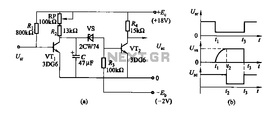
The delay time ranges from 0.5 to 3.5 seconds, which can be adjusted using the potentiometer RP to modify the delay duration. The circuit utilizes a timing mechanism that allows for the adjustment of delay intervals between 0.5 seconds and...
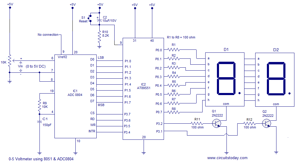
A simple 0-5 digital voltmeter utilizing the 8051 (AT89S51 microcontroller) is presented, accompanied by a circuit diagram and assembly language (ASM) code. This digital voltmeter is designed for straightforward voltage measurement. The circuit employs an AT89S51 microcontroller, which serves as...
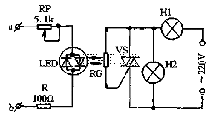
The circuit for a two-color music lantern controller is illustrated in Figure 1-44 below. Terminals a and b are located at both ends of the speaker, which receives audio signals. The audio signal is processed through a sensitivity adjustment...
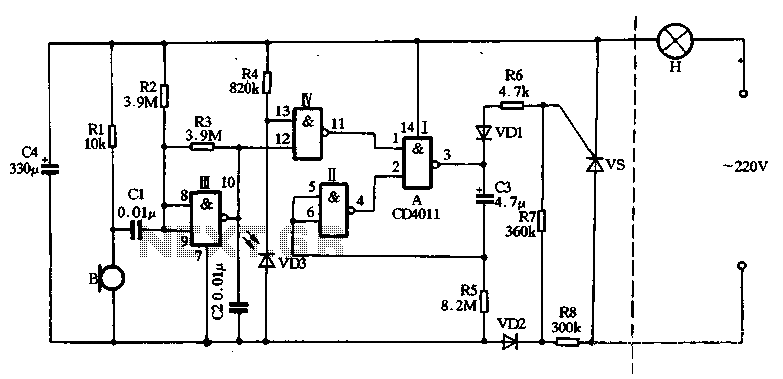
The main circuit utilizes a two-input NAND gate composed of four digital integrated circuits. This includes a NAND gate microphone amplifier circuit, a light control mechanism using an "AND gate," and a monostable delay control circuit formed by NAND...
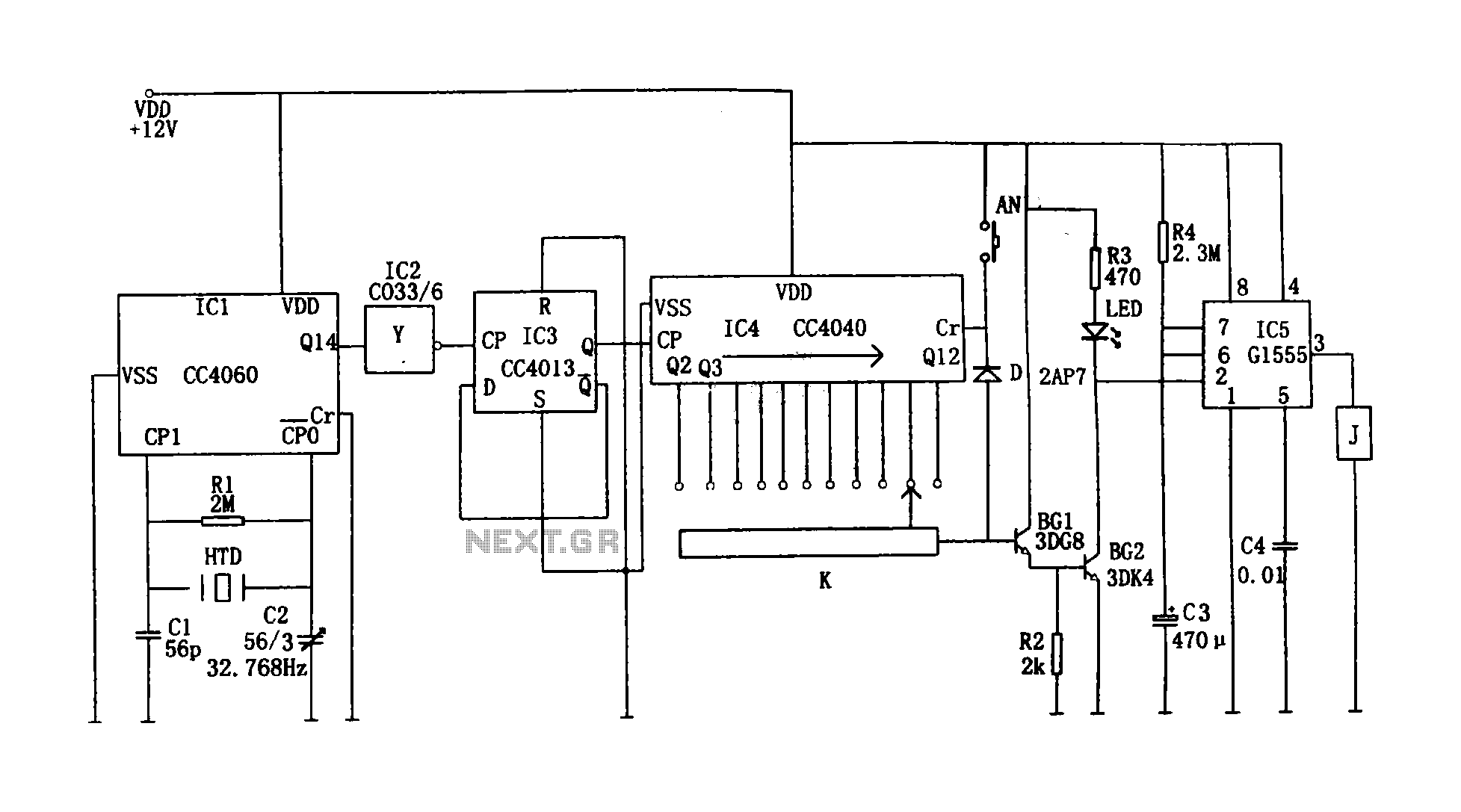
This circuit illustrates a precision digital timing control system. The controller includes a crystal oscillator circuit, a divider, a counting circuit, and monostable flip-flops. The crystal oscillator circuit features a series of 14 binary counters/dividers, a watch crystal operating...
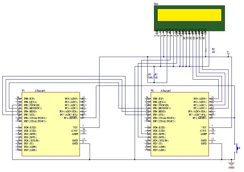
This document outlines the process of transmitting data between a PC and an AVR Atmega8 microcontroller using the USART module. The communication utilizes the COM port of the PC, which is based on the RS232 protocol, and the UART...
Warning: include(partials/cookie-banner.php): Failed to open stream: Permission denied in /var/www/html/nextgr/view-circuit.php on line 713
Warning: include(): Failed opening 'partials/cookie-banner.php' for inclusion (include_path='.:/usr/share/php') in /var/www/html/nextgr/view-circuit.php on line 713