
Missing pulse detector circuit using NE555

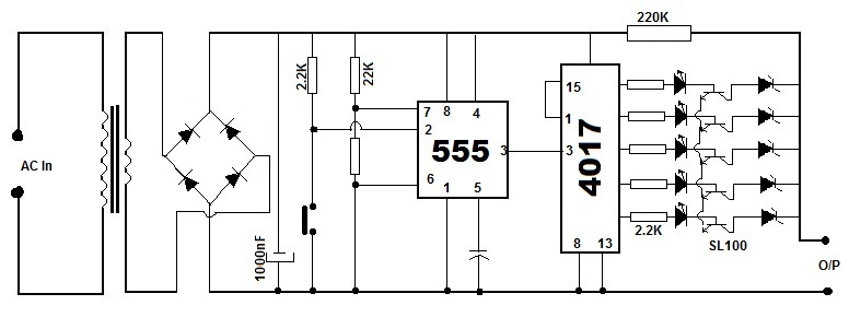
The NE555 timer IC operates in monostable mode, where it generates a single output pulse in response to an input trigger. In this application, the timer is set up to monitor the frequency of incoming pulse signals. The pickup transducer captures the relevant signal, which is then processed to produce a clean negative-going pulse. This pulse is fed into pin 2 of the NE555, which serves as the trigger input. The timing interval is determined by external resistors and capacitors connected to the IC, which define how long the output remains high after being triggered.
When the pulse frequency is above a certain threshold, the IC continuously resets the timing cycle, keeping the output low. However, if the pulse frequency decreases or if a pulse is missing, the timing capacitor begins to charge, and once it reaches a specific voltage level, the output of the NE555 transitions to a high state. This change in output can be used to signal an alarm or activate additional circuitry, thereby indicating a fault condition, such as a malfunctioning spark plug or an abnormal heartbeat.
Transistor T1 plays a crucial role in discharging the timing capacitor, allowing for rapid reset of the timing interval. The choice of components, including the timing capacitor and resistors, is critical in setting the sensitivity and response time of the circuit. This design can be further refined by adjusting the component values to suit specific applications, ensuring reliable detection of missing pulses or irregular intervals in various monitoring scenarios.An NE555 timer IC connected as shown here can detect a missing pulse or abnormally long period between two consecutive pulses in a train of pulses. Such circuits can be used to detect the intermittent firing of the spark plug of an automobile or to monitor the heart beat of a sick patient.
The signal from the pick up transducer is shaped to form a negative going pulse and is applied to pin 2 of the IC which is connected as a mono stable. As long as the spacing between the pulse is less than the timing interval, the timing cycle is continuously reset by the input pulses and the capacitor is discharged via T1. A decrease in pulse frequency or a missing pulse permits completion of time interval which causes a change in the output level.
🔗 External reference
Related Circuits
Battery eliminators are circuits that create a DC power supply from AC mains. Essentially, battery eliminator circuits consist of a step-down transformer, rectifier, and voltage regulator. A simple circuit of a multipurpose battery eliminator features various output voltage ranges...
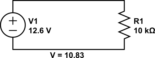
Connect a 12V fan to this circuit that consumes 70mA (0.07A), ensuring the circuit can supply at least that amount of current. There appears to be a misunderstanding regarding the analysis. The voltage drop across the resistor equals the...
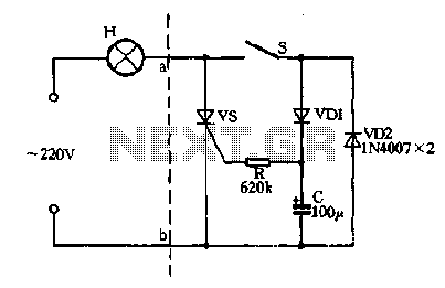
Closing the switch S allows the AC positive half-cycle to flow through diode VDI and resistor R, causing the SCR to open simultaneously at both ends of the capacitor C, which becomes fully charged. During this phase, the positive...
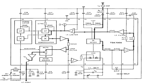
The TDA7000 is an integrated circuit (IC) designed for FM portable radios, featuring a Frequency-Locked Loop (FLL) system with an intermediate frequency of 70 kHz. It incorporates several functions, including an RF input stage, mixer, local oscillator, IF demodulator,...
A DC-coupled multi-stage amplifier circuit consists of multiple stages of amplification using a DC-coupled configuration. Each stage utilizes NPN-type transistors, which are designed to maintain appropriate operating points at the base of each stage. As the signal progresses through...
This weblog focuses on electronic circuit schematics, PCB design, DIY kits, and diagrams for various electronic projects. It features a mixer that demonstrates how to create microphone pre-amplifiers suitable for both low and high impedance microphones. The design utilizes...
Warning: include(partials/cookie-banner.php): Failed to open stream: Permission denied in /var/www/html/nextgr/view-circuit.php on line 713
Warning: include(): Failed opening 'partials/cookie-banner.php' for inclusion (include_path='.:/usr/share/php') in /var/www/html/nextgr/view-circuit.php on line 713