
Mixed-Circuits
This circuit functions as a simple analog-to-digital interface with a resolution capability of 10 to 12 bits. A 10-bit resolution translates to 1024 counts or divisions of a full scale (FS), which is approximately equivalent to 3.5 digits or 1999 counts. In this setup, 1 V can be represented as 1.000 V, allowing for the resolution of even 1 mV for a full scale of 1 V. Capacitors C6 and others should be plastic multilayer low-leakage types to ensure accurate readings. It is recommended to use 1% metal film resistors with a temperature coefficient of 100 ppm or better. The design gain of operational amplifier U1B should be tailored to the desired full scale. The output frequency (Fout) is directly related to the input values.
Additionally, this circuit utilizes an R-2R digital-to-analog converter (DAC), which converts an 8-bit byte into an analog value. The converter provides 256 levels, including zero. It can be employed to transform a byte from a microcontroller into an analog value, such as 1.51 V. At full scale, when all 8 bits are set high, the calibration yields 2.55 V, with each bit increment corresponding to 0.01 V or 10 mV steps. If the eight-bit inputs are sourced from a counter, a staircase waveform will be observed at the output, with each step reflecting a 10 mV increase or decrease based on the counting direction.
The CD4538 component is a dual monostable multivibrator. Upon triggering, it generates a single pulse or a high-low event. The T+ pin (pin 4 of U1a) serves as the positive edge trigger input, while the T- pin (pin 5) functions as the negative edge trigger input. When a pulse is applied to pin 5, the falling edge transitions the output at pin 6 from low to high, maintaining this state for a duration defined by T = R2 * C1.
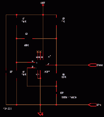
The LM311 operates as a comparator, functioning with a single 5V supply or dual supplies. It has an input current of 150 nA and can drive outputs between -50 V and +50 mA. The output is TTL-CMOS compatible and is configured as an open collector, allowing it to sink current but not source it. A pull-up resistor (R2) is used to establish the output state. The output condition is determined by the relative voltages at the non-inverting and inverting inputs; if the non-inverting input is more positive, the LM311 output remains in a high impedance state, as the output transistor is turned off.
This circuit is based on an older application note from Exar, where the frequency is determined by IC1 and IC2, while potentiometer P1 controls the duty cycle. To achieve the desired frequency, calculations for resistor and capacitor values are necessary, following the guidelines in the LM555 datasheet. It is encouraged to analyze the circuit further and innovate beyond the original design, as mere replication serves only as a learning tool. The provided Eagle circuit can be modified for educational purposes, and PCB design is also recommended for practical implementation.This Circuit is a simple Analog to Digital Interface with a capability of 10 to 12 bits resolution. 10 bits means 1024 counts or parts of a full scale FS which is close to 3-1/2 1999 counts. In this 1 V can be read as 1. 000 V that means even 1mV can be resolved for FS of 1V. The Caps C6 and others must be plastic multilayer low-leakage types for a ccuracy of reading. Use all 1% MFR 100ppm or better resistors, Design gain of U1B for the Full Scale you want. The Output Fout is a Frequency which is directly Read More This is a R-2R Digital to Analog Converter, It converts a byte (8 bit) to a analog value. It has 256 levels including zero. This can be used to convert a byte sent from a microcontroller to a analog value like say 1. 51 V. At full scale, when all 8 bits are high calibrate to give 2. 55 V then ever bit increment is 0. 01V, 10mV steps. If the eight bits inputs are from a counter you then will see a staircase waveform at output, each step being 10mV higher or lower depending on whether the counter is counting up or Read More CD4538 is a dual Monostable Multivibrator.
When you trigger the chip the output sends off one single pulse or one high-low event. The T+ pin 4 of U1a is the positive edge trigger or raising edge trigger input, the T- pin 5 is falling edge or negative edge trigger input. Now see the image of the single pulse above which shows both the edges, If this is the input pulse at pin 5 then the falling edge turns the output pin 6 from low to high, this output remains high for time T = R2 * C1 and then goes Read More LM311 is a comparator, It operates from single 5V supply or dual supplies, input current 150 nA, 50 V-50 mA output drive capability.
TTL-CMOS compatible output. The Output is open collector so it can sink current but cannot source, a totem pole output can source and sink. In this Circuit R2 is the source or pull-up. The Output being high or low depends on which input is more dominant or positive. If + or non-inverting input is more positive than the inverting input then output of LM311 is high impedance or high Z as output transistor of LM311 is turned Read More This circuit is based on a very old application note from exar, in this the frequency is fixed by IC1 and IC2 -P1 controls the duty cycle.
you need to compute the R and C values to get what you need, LM555 data sheet. You have to study the circuit and do something more innovative perhaps, just copying is ok for learning but it will get you nowhere, so learn and then innovate, the eagle circuit is given below so you can learn by editing it, also design a PCB with it, and you can even make a PCB at Read More 🔗 External reference
Additionally, this circuit utilizes an R-2R digital-to-analog converter (DAC), which converts an 8-bit byte into an analog value. The converter provides 256 levels, including zero. It can be employed to transform a byte from a microcontroller into an analog value, such as 1.51 V. At full scale, when all 8 bits are set high, the calibration yields 2.55 V, with each bit increment corresponding to 0.01 V or 10 mV steps. If the eight-bit inputs are sourced from a counter, a staircase waveform will be observed at the output, with each step reflecting a 10 mV increase or decrease based on the counting direction.
The CD4538 component is a dual monostable multivibrator. Upon triggering, it generates a single pulse or a high-low event. The T+ pin (pin 4 of U1a) serves as the positive edge trigger input, while the T- pin (pin 5) functions as the negative edge trigger input. When a pulse is applied to pin 5, the falling edge transitions the output at pin 6 from low to high, maintaining this state for a duration defined by T = R2 * C1.
The LM311 operates as a comparator, functioning with a single 5V supply or dual supplies. It has an input current of 150 nA and can drive outputs between -50 V and +50 mA. The output is TTL-CMOS compatible and is configured as an open collector, allowing it to sink current but not source it. A pull-up resistor (R2) is used to establish the output state. The output condition is determined by the relative voltages at the non-inverting and inverting inputs; if the non-inverting input is more positive, the LM311 output remains in a high impedance state, as the output transistor is turned off.
This circuit is based on an older application note from Exar, where the frequency is determined by IC1 and IC2, while potentiometer P1 controls the duty cycle. To achieve the desired frequency, calculations for resistor and capacitor values are necessary, following the guidelines in the LM555 datasheet. It is encouraged to analyze the circuit further and innovate beyond the original design, as mere replication serves only as a learning tool. The provided Eagle circuit can be modified for educational purposes, and PCB design is also recommended for practical implementation.This Circuit is a simple Analog to Digital Interface with a capability of 10 to 12 bits resolution. 10 bits means 1024 counts or parts of a full scale FS which is close to 3-1/2 1999 counts. In this 1 V can be read as 1. 000 V that means even 1mV can be resolved for FS of 1V. The Caps C6 and others must be plastic multilayer low-leakage types for a ccuracy of reading. Use all 1% MFR 100ppm or better resistors, Design gain of U1B for the Full Scale you want. The Output Fout is a Frequency which is directly Read More This is a R-2R Digital to Analog Converter, It converts a byte (8 bit) to a analog value. It has 256 levels including zero. This can be used to convert a byte sent from a microcontroller to a analog value like say 1. 51 V. At full scale, when all 8 bits are high calibrate to give 2. 55 V then ever bit increment is 0. 01V, 10mV steps. If the eight bits inputs are from a counter you then will see a staircase waveform at output, each step being 10mV higher or lower depending on whether the counter is counting up or Read More CD4538 is a dual Monostable Multivibrator.
When you trigger the chip the output sends off one single pulse or one high-low event. The T+ pin 4 of U1a is the positive edge trigger or raising edge trigger input, the T- pin 5 is falling edge or negative edge trigger input. Now see the image of the single pulse above which shows both the edges, If this is the input pulse at pin 5 then the falling edge turns the output pin 6 from low to high, this output remains high for time T = R2 * C1 and then goes Read More LM311 is a comparator, It operates from single 5V supply or dual supplies, input current 150 nA, 50 V-50 mA output drive capability.
TTL-CMOS compatible output. The Output is open collector so it can sink current but cannot source, a totem pole output can source and sink. In this Circuit R2 is the source or pull-up. The Output being high or low depends on which input is more dominant or positive. If + or non-inverting input is more positive than the inverting input then output of LM311 is high impedance or high Z as output transistor of LM311 is turned Read More This circuit is based on a very old application note from exar, in this the frequency is fixed by IC1 and IC2 -P1 controls the duty cycle.
you need to compute the R and C values to get what you need, LM555 data sheet. You have to study the circuit and do something more innovative perhaps, just copying is ok for learning but it will get you nowhere, so learn and then innovate, the eagle circuit is given below so you can learn by editing it, also design a PCB with it, and you can even make a PCB at Read More 🔗 External reference