
Mobile Bug Detector
T he circuit can detect both the incoming and outgoing calls, SMS and video transmission even if the mobile phone is kept in the silent mode. The moment the bug detects RF transmission signal from an activated mobile phone, it starts sounding a beep alarm and the LED blinks.
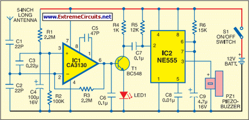
The alarm continues until the signal transmission ceases. An ordinary RF detector using tuned LC circuits is not suitable for detecting signals in the GHz frequency band used in mobile phones. The transmission frequency of mobile phones ranges from 0. 9 to 3 GHz with a wavelength of 3. 3 to 10 cm. So a circuit detecting gigahertz signals is required for a mobile bug. Here the circuit uses a 0. 22 F disk capacitor (C3) to capture the RF signals from the mobile phone. The lead length of the capacitor is fixed as 18 mm with a spacing of 8 mm between the leads to get the desired frequency.
The disk capacitor along with the leads acts as a small gigahertz loop antenna to collect the RF signals from the mobile phone. Op-amp IC CA3130 (IC1) is used in the circuit as a current-to-voltage converter with capacitor C3 connected between its inverting and non-inverting inputs.
It is a CMOS version using gate-protected p-channel MOSFET transistors in the input to provide very high input impedance, very low input current and very high speed of performance. The output CMOS transistor is capable of swinging the output voltage to within 10 mV of either supply voltage terminal.
Capacitor C3 in conjunction with the lead inductance acts as a transmission line that intercepts the signals from the mobile phone. This capacitor creates a field, stores energy and transfers the stored energy in the form of minute current to the inputs of IC1.
This will upset the balanced input of IC1 and convert the current into the corresponding output voltage. Capacitor C4 along with high-value resistor R1 keeps the non-inverting input stable for easy swing of the output to high state.
Resistor R2 provides the discharge path for capacitor C4. Feedback resistor R3 makes the inverting input high when the output becomes high. Capacitor C5 (47pF) is connected across strobe` (pin 8) and null` inputs (pin 1) of IC1 for phase compensation and gain control to optimize the frequency response. When the mobile phone signal is detected by C3, the output of IC1 becomes high and low alternately according to the frequency of the signal as indicated by LED1.
This triggers monostable timer IC2 through capacitor C7. Capacitor C6 maintains the base bias of transistor T1 for fast switching action. The low-value timing components R6 and C9 produce very short time delay to avoid audio nuisance. Assemble the circuit on a general-purpose PCB as compact as possible and enclose in a small box like junk mobile case. As mentioned earlier, capacitor C3 should have a lead length of 18 mm with lead spacing of 8 mm. Carefully solder the capacitor in standing position with equal spacing of the leads. The response can be optimized by trimming the lead length of C3 for the desired frequency. You may use a short telescopic type antenna. Use the miniature 12V battery of a remote control and a small buzzer to make the gadget pocket-size. The unit will give the warning indication if someone uses mobile phone within a radius of 1. 5 meters. 🔗 External reference
Related Circuits
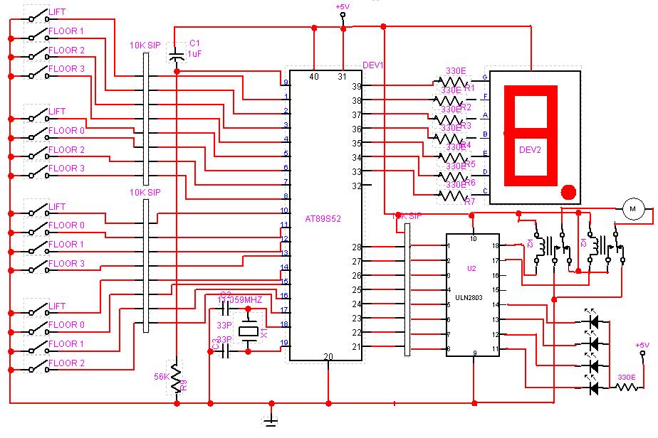
A circuit design has been conceptualized, and an Assembly code program has been drafted for a three-level mini system. The described circuit design focuses on a three-level mini system, which can be interpreted as a hierarchical structure where each level...
A simple proximity detector can be created using this electronic circuit. This circuit responds to the presence of a conductive object within a specific range. The sensitivity of the circuit can be adjusted with potentiometer P1 to achieve the...
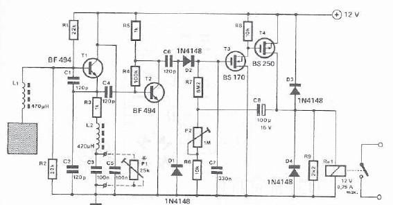
This bugg is based on my previous 3-transistor transmitter. This bugg unit has many advantages. The transmitter uses a crystal 46.515MHz to hold a steady frequency. The frequency can be fine-tuned by some 100kHz. The transmitter can send data...
This circuit is a two-wire light level detector, which does not separate the wires for power supply and output signal delivery. It operates using a current loop that performs both functions over a single pair of cables, requiring only...
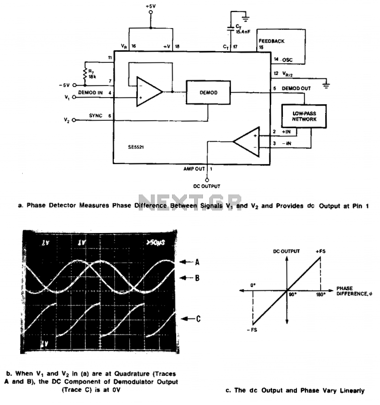
Signals of identical frequency are applied to the sync input (Pin 6) and to the demodulator input (Pin 4). The demodulator operates as a phase detector, with the output DC component being proportional to the phase difference between the...
The cooling is not only a PC using a small fan with an electronic commutator. A special feature of these fans is that their removal is less dependent on the load. Indicators monitoring the DC component of current may...
Warning: include(partials/cookie-banner.php): Failed to open stream: Permission denied in /var/www/html/nextgr/view-circuit.php on line 713
Warning: include(): Failed opening 'partials/cookie-banner.php' for inclusion (include_path='.:/usr/share/php') in /var/www/html/nextgr/view-circuit.php on line 713