
mobile incoming call indicator
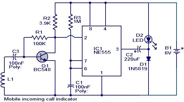
This circuit employs a simple yet effective design to provide a visual alert for incoming mobile phone calls. The core component of the circuit is the NE555 timer IC, which operates in monostable mode triggered by the activation of transistor Q1. The transistor serves as a switch, allowing current to flow from the power source to the LED when a signal is detected.
The coil L1 acts as an inductive sensor, picking up the electromagnetic waves emitted by the mobile phone's transmitter when a call is incoming. The construction of this coil is critical; it must be precisely wound to achieve the necessary inductance for optimal performance. The choice of 36 SWG enameled copper wire is appropriate due to its balance of flexibility and conductivity, allowing for efficient signal capture.
The NE555 timer is configured such that when pin 2 receives a low signal from the collector of Q1, it triggers the output at pin 3 to go high momentarily, turning on the LED. The duration of the LED's blinking can be adjusted by changing the resistor and capacitor values connected to the NE555, allowing for customization based on user preference.
This circuit is particularly useful in environments where mobile phone ringtones may be disruptive, providing an alternative notification method that is both discreet and effective. The simplicity of the design makes it accessible for hobbyists and professionals alike, ensuring that it can be constructed with minimal components while still delivering reliable performance.This circuit can be used to escape from the nuisance of mobile phone rings when you are at home. This circuit will give a visual indication if placed near a mobile phone even if the ringer is deactivated. When a call is coming to the mobile phone, the transmitter inside it becomes activated. The frequency of the transmitter is around 900MHz. The co il L1 picks up these oscillations by induction and feds it to the base of Q1. This makes the transistor Q1 activated. Since the Collector of Q1 is connected to the pin 2 of IC1 (NE555), the IC1 is triggered to make the LED connected at its output pin (pin 3) to blink. The blinking of the LED is the indication of incoming call. The coil L1 can be made by making 150 turns of 36 SWG enameled copper wire on a 5mm dia plastic former.
Or you can purchase a 10 uH coil from shop if available. 🔗 External reference
Related Circuits
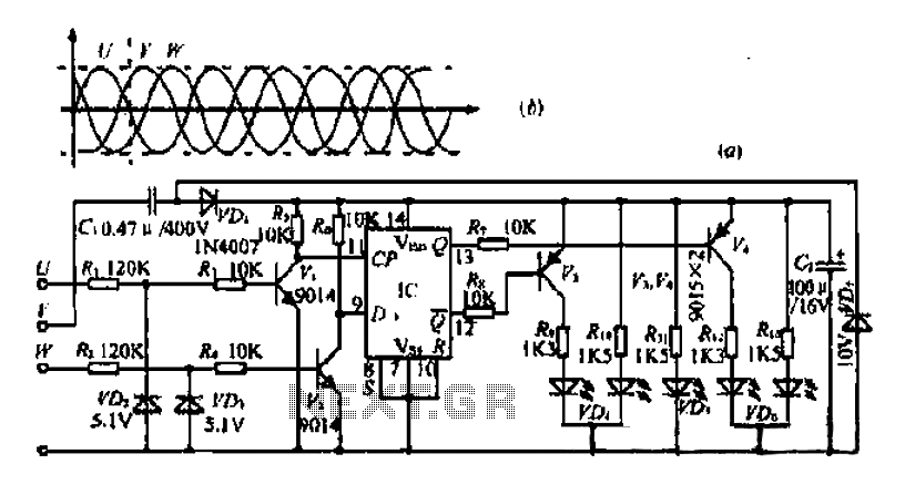
The three-phase voltage waveform diagram illustrates that when one phase voltage transitions from positive to negative across the zero point, the subsequent phase voltage becomes positive while the third phase remains negative. The U terminal voltage is positive when...
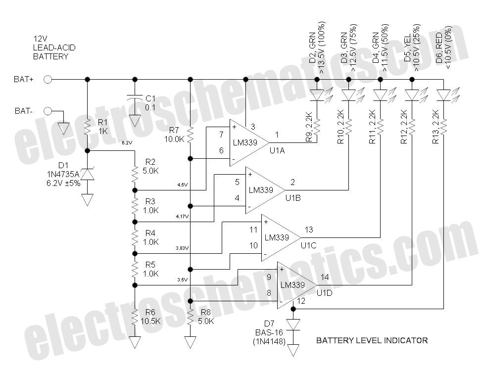
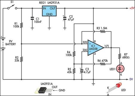
This battery level indicator features five LEDs that illuminate progressively as the voltage increases: Red indicates power connection (0%), Yellow signifies voltage greater than 10.5V (25%). The battery level indicator circuit utilizes a series of five light-emitting diodes (LEDs) to...
This design integrates power-on and low-battery indications, capable of operating with any battery voltage up to 15V. It features a very low current drain of 2mA or less and costs less than $3.50 with new components. When the battery...
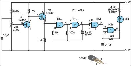
This circuit indicates the remaining battery life by varying the duty cycle and flash rate of an LED as the battery voltage decreases. It indicates five battery conditions: (1) a steady glow indicates that the battery is healthy; (2)...
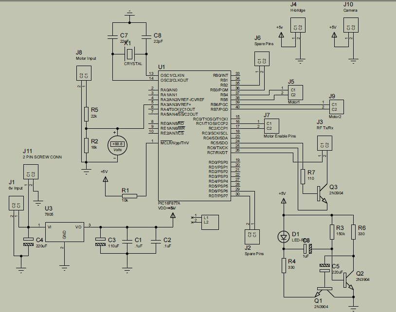
The project is developed by Team Stark, with Gilbert as the leader and team members Martin and Janssen. The tasks have been divided into three parts. The first part includes camera control, login database, installer, and network setup, which...
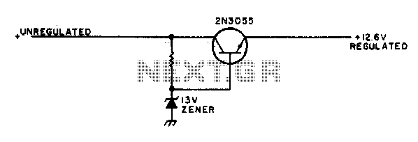
This simple mobile voltage regulator circuit may save your two-meter or CB transceiver if the voltage regulator fails. The 2N3055 should be heat-sinked if the current drawn by the rig exceeds 2 A during transmission. This circuit will do...
Warning: include(partials/cookie-banner.php): Failed to open stream: Permission denied in /var/www/html/nextgr/view-circuit.php on line 713
Warning: include(): Failed opening 'partials/cookie-banner.php' for inclusion (include_path='.:/usr/share/php') in /var/www/html/nextgr/view-circuit.php on line 713