
Modular Burglar Alarm
This circuit design is structured to enhance security through its automatic exit and entry features, combined with a robust tamper protection system. The integration of both normally-closed and normally-open contacts allows for flexibility in installation, catering to various sensor types and user preferences. The 12-volt supply connection ensures consistent power, enabling reliable operation of all components.
The timed exit and entry delays are critical for users, providing a grace period during which they can safely exit or enter the premises without triggering an alarm. The buzzer serves as an audible alert, reinforcing the need to complete the exit or entry process within the designated timeframe. The functionality of the main bell, which can be silenced at any moment, adds an additional layer of user control, ensuring that false alarms can be managed effectively.
The 24-hour personal attack/tamper zone, supported by the SCR/thyristor, is particularly significant in high-security environments. The immediate response to any tampering attempts ensures that security is maintained at all times, with the capability to reset the system quickly through SW2. This feature is essential for maintaining operational integrity after a security event.
The expansion modules are a vital aspect of this circuit, as they provide scalability to the system. Users can customize their security setup according to their specific needs, adding zones as required. The ability to identify which zone has been activated enhances troubleshooting and response efforts, making it easier to address potential security breaches.
Overall, this circuit is designed for versatility and reliability, making it suitable for a wide range of applications in security systems. The clear indication of alarm status through LEDs and the shared reset functionality across modules contribute to an intuitive user experience, ensuring that the system remains effective in protecting the premises.This circuit features automatic Exit and Entry delays and a timed Bell Cut-off. It has provision for both normally-closed and normally-open contacts, and a 24-hour Personal Attack/Tamper zone. It is connected permanently to the 12-volt supply and its operation is "enabled" by opening SW1. By using the expansion modules, you can add as many zones a s you require; some or all of which may be the inertia (shock) sensor type. All the green LEDs should be lighting before you open SW1. You then have up to about a minute to leave the building. As you do so, the Buzzer will sound. It should stop sounding when you shut the door behind you. This indicates that the Exit/Entry loop has been successfully restored within the time allowed. When you re-enter the building you have up to about a minute to move SW1 to the off position. If SW1 is not switched off in time, the relay will energise and sound the main bell. It will ring for up to about 40 minutes. But it can be turned off at any time by SW1. The "Instant" zone has no Entry Delay. If you don`t want to use N/O switches, leave out R8, C8 and Q2; and fit a link between Led 3 and C7. The 24 Hour PA/Tamper protection is provided by the SCR/Thyristor. If any of the switches in the N/C loop is opened, R11 will trigger the SCR and the bell will ring. In this case the bell has no time limit. Once the loop is closed again, the SCR may be reset by pressing SW2 and temporarily interrupting the current flow. The basic circuit will be satisfactory in many situations. However, it`s much easier to find a fault when the alarm is divided into zones and the control panel can remember which zone has caused the activation.
The expansion modules are designed to do this. Although they will work with the existing instant zone, they are intended to replace it. When a zone is activated, its red LED will light and remain lit until the reset button is pressed. All the modules can share a single reset button. 🔗 External reference
Related Circuits
This page outlines how to create a simple theft deterrent that can be quite effective. The concept involves using a flashing red LED to indicate that the vehicle is protected. This device serves to safeguard the car from potential...
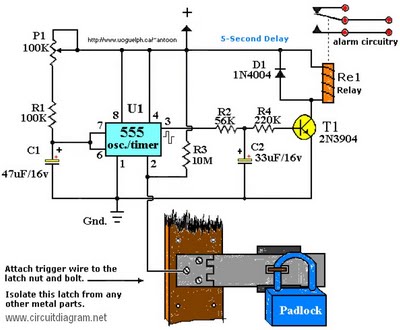
The operating voltage for capacitors C1 and C2 should be raised to 25V if a 12V energy source is used. A general guideline is that the operating voltage of capacitors should be at least double the supplied voltage; for...
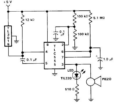
This door open alarm electronic project is designed using a linear hall effect device and a 555 timer circuit. The project utilizes the TL3103 linear hall effect device for detecting the angle of rotation. The TL3103 is positioned within...
This simple circuit can be used to protect a bike from theft. It produces a loud alarm tone if someone attempts to start the bike. The alarm can only be disabled when the hidden switch S2 is opened. The...
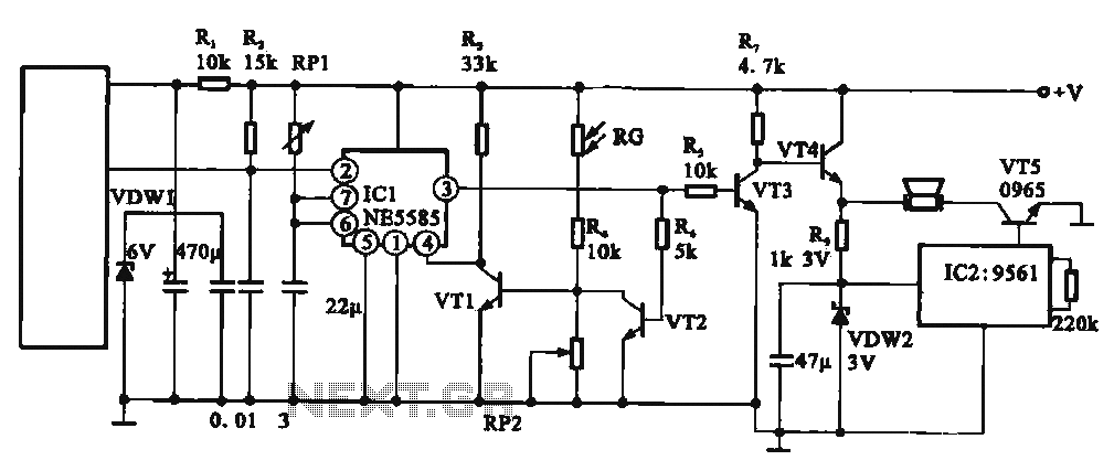
This circuit illustrates an automatic unattended burglar alarm system designed primarily for residential use, warehouses, and similar applications. The circuit features a pyroelectric infrared sensor integrated with a light control mechanism. It comprises components such as resistors (RG, RP2,...
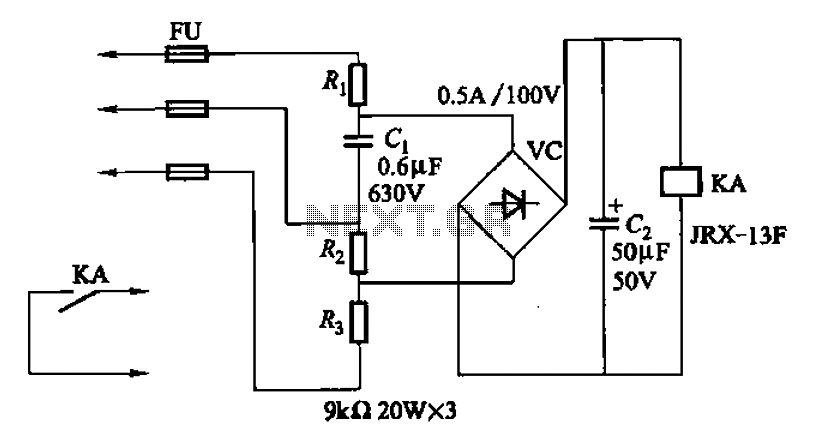
A capacitor C1 and resistors R1-R3 form a negative sequence voltage filtration device. The resistors and capacitors must meet the following requirements: R1, R2, R3 = 5.5/C1 (KN). The relationship between the resistance and capacitance values is arbitrary. Capacitor...