
Modular Headphone Amplifier
The Headphone Amplifier circuit utilizes two NE5532 operational amplifiers to achieve its design goals. The first op-amp, IC1B, is configured as a master amplifier, which features a non-inverting configuration that ensures high input impedance and low output impedance, making it suitable for driving headphones directly. The second op-amp, IC1A, acts as a unity-gain buffer, effectively isolating the output of the master amplifier from the load. This arrangement allows for increased current drive capability, essential for powering low-impedance headphones.
The design incorporates two headphone outputs, J3 and J4, allowing for simultaneous listening by multiple users or providing a backup output. The low AC gain of the amplifier is a deliberate choice, as it is intended to receive a signal from the Control Center module, which is responsible for providing the necessary gain to drive the subsequent power amplifier. For applications where the Headphone Amplifier operates independently, adjusting the resistor R1 to 1.5kΩ increases the gain to 9, which is suitable for most consumer audio devices.
The power supply design employs two 9V regulator ICs instead of the 15V regulators used in other modules. This choice is based on the NE5532's ability to maintain consistent output levels even when driving low-impedance loads, thus optimizing performance while minimizing heat dissipation. The ±9V supply configuration enhances the amplifier's efficiency, particularly near the clipping threshold, where distortion can occur.
For connectivity, the input socket is designed to connect directly to the Main Out of the Control Center Module, ensuring seamless integration within the modular system. The provision of an additional socket (J2) allows for flexible routing of the audio signal, accommodating various configurations as required by the user.
The physical design of the amplifier allows for easy integration into standard enclosures, with Hammond extruded aluminum cases being recommended. These cases not only provide adequate protection for the circuit boards but also offer an attractive appearance when stacked, enhancing the overall aesthetic of the audio system. The specified dimensions of 16 x 10.3 x 5.3 cm or 22 x 10.3 x 5.3 cm are optimal for housing the amplifier boards, ensuring a neat and professional finish for any audio setup.Those wanting private listening to their music program should add this Headphone Amplifier to the Modular Preamplifier chain. The circuit was kept as simple as possible compatibly with a High Quality performance. This goal was achieved by using two NE5532 Op-Amps in a circuit where IC1B is the "master" amplifier wired in the common non-inverting c
onfiguration already used in the Control Center Line amplifier. IC1A is the "slave" amplifier and is configured as a unity-gain buffer: parallel amplifiers increase output current capability of the circuit. Two Headphone outputs are provided by J3 and J4. The ac gain of the amplifier was kept deliberately low because this module is intended to be connected after the Control Center module, which provides the gain sufficient to drive the power amplifier.
If you intend to use this Headphone Amplifier as a stand-alone device, a higher ac gain could be necessary in order to cope with a CD player or Tuner output. This is accomplished by lowering the value of R1 to 1K5. In this way an ac gain of 9 is obtained, more than sufficient for the purpose. Contrary to the two 15V positive and negative regulator ICs used in other modules of this preamp, two 9V devices were employed instead.
This because the NE5532 automatically limits its output voltage into very low loads as 32 Ohm in such a way that the output amplitude of the amplified signal remains the same, either the circuit is powered at ±9V or ±15V. The choice of a ±9V supply allows less power dissipation and better performance of the amplifier close to the clipping point.
The input socket of this amplifier must be connected to the Main Out socket of the Control Center Module. As this output is usually reserved to drive the power amplifier, a second socket (J2) wired in parallel to J1 is provided for this purpose.
As with the other modules of this series, each electronic board can be fitted into a standard enclosure: Hammond extruded aluminum cases are well suited to host the boards of this preamp. In particular, the cases sized 16 x 10. 3 x 5. 3 cm or 22 x 10. 3 x 5. 3 cm have a very good look when stacked. See below an example of the possible arrangement of the front and rear panels of this module. 🔗 External reference
Related Circuits
This is a rather unusual QRP Power Amplifier design, with a wide frequency response; within three dB's from 300KHz to 30MHz. Overall gain is in the region of 16dB and the final output power may be well over four...
A friend is interested in building a hi-fi power amplifier, specifically a Class AB model due to its quality sound, particularly in bass response and distinct clarity. This circuit is designed as a hi-fi OCL (Output Capacitor-Less) power amplifier...
Figure 1 illustrates the schematic for a universal input, 7.6 V, 700 mA constant voltage/constant current (CV/CC) power supply designed for LED driver applications. This design employs the LinkSwitch-II product LNK606PG in a flyback configuration. The LNK606PG (U1) integrates...
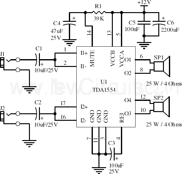
This document presents a 22-watt stereo audio power amplifier circuit diagram utilizing the TDA1554 integrated circuit from NXP Semiconductors (formerly known as PHILIPS Semiconductors). The circuit is designed to amplify stereo signals effectively. It dissipates approximately 28 watts of...
This design addresses the limitations of the microphone preamp in the Sony R91, which clips at low levels, providing only 28mV of headroom for an input that may reach 1800mV, depending on the microphone and volume settings. The design...
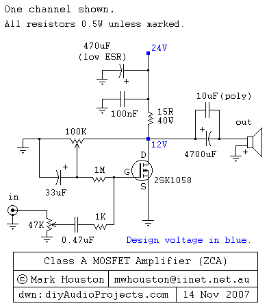
This weblog discusses electronic circuit schematics, PCB design, DIY kits, and electronic project diagrams. It features a simple Class A MOSFET amplifier using the 2SK1058 component. The circuit operates with a 24V supply voltage at high current. It incorporates...
Warning: include(partials/cookie-banner.php): Failed to open stream: Permission denied in /var/www/html/nextgr/view-circuit.php on line 713
Warning: include(): Failed opening 'partials/cookie-banner.php' for inclusion (include_path='.:/usr/share/php') in /var/www/html/nextgr/view-circuit.php on line 713