
Modular Signal System Implementation
The Modular Signal System is designed to enhance the operation of model railroads by integrating efficient signaling and detection mechanisms. The cascade modules serve as the primary interface for signal management, while the detection modules play a critical role in monitoring track occupancy.
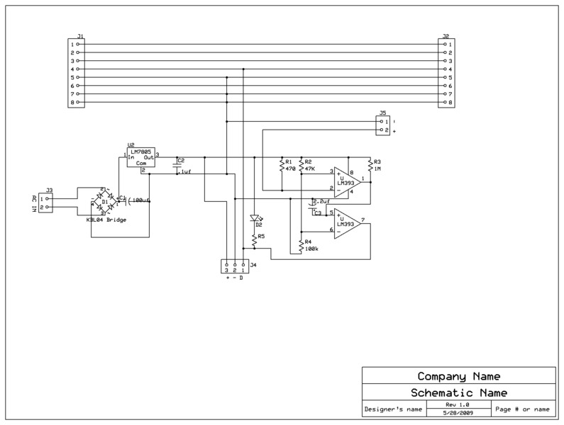
The circuit board for the cascade module is specifically engineered to accommodate the necessary connections for signal control boards, allowing for seamless communication between the signals and the detection systems. Each cascade module can influence two blocks, ensuring that signals accurately reflect the state of the track ahead.
The optical detection system, based on Rob Paisley’s BOD, employs light sensors to determine the presence of a train on the track. This method provides a reliable means of occupancy detection, which is crucial in a modular setup where varying equipment configurations may exist among different participants. The incorporation of current-sensing detectors further enhances the reliability of the system, ensuring that all rolling stock is monitored effectively.
Power management within the circuit is facilitated by a 5V DC power supply, which is essential for the operation of both the detectors and the signaling components. This power supply is integrated into each circuit board, ensuring that all elements function harmoniously within the system.
Careful consideration is given to the layout and design of the circuit boards to minimize interference and maximize performance. The use of high-quality components and a robust design approach ensures that the system remains reliable under varying operational conditions.
Overall, this project exemplifies a thoughtful integration of technology and design principles to create a modular signaling system that enhances the operational capabilities of model railroads. The detailed circuit designs and operational principles outlined herein provide a comprehensive understanding of the system's functionality and application.This page serves as documentation for the circuits that I have built which make use of the Modular Signal System first documented by Gregg Fuhriman in Railmodel Journal, and further documented on the Free-mo. org website. This effort was an experiment on my part in designing and building a circuit board for the circuits involved.
This effort docu ments two circuit board designs, one for cascade modules, where signals are located, and a second for detection modules, which go between the cascade modules. These terms are further explained in the link above. The Modular signal system requires a combination of optical and current sensing detectors for reliable operation.
This is required on a modular layout becauase we cannot assume that every participant will have resistor equiped wheelsetson all rolling stock. For this project, I used Rob Paisley`s Block Occupancy Detector helper as the optical detector. I incorporated a BOD helper into each of the circuit boards, along with a 5vDC power supply for powering the detectors and the signals at cascade modules.
The cascade circuit includes BOD helper and outputs to connect signals control boards for each of the two blocks the cascade module influences. The circuit details are below: 🔗 External reference
Related Circuits
The FKL-32 type automatic thyristor excitation device is designed for synchronous generators with a terminal voltage of 400V and a capacity of 500kW and below. It is used for the automatic adjustment of excitation. The FKL-32 thyristor excitation device is...
Instructions for utilizing an existing infrared transmitter from any room within the house. The concept is straightforward and operates more effectively than anticipated. This project proves to be quite useful, allowing control over devices from virtually anywhere. For instance,...

This section outlines the various systems on board the Chinook II. The approach taken is to utilize reliable and appropriate systems that align with the boat's size and intended use. The design incorporates elements that may deviate from standard...
This circuit converts a mono audio signal into a stereo signal that can be panned between the left and right channels using a 0-10V control signal. It is designed for analog synthesizer systems. The circuit operates by taking a single...
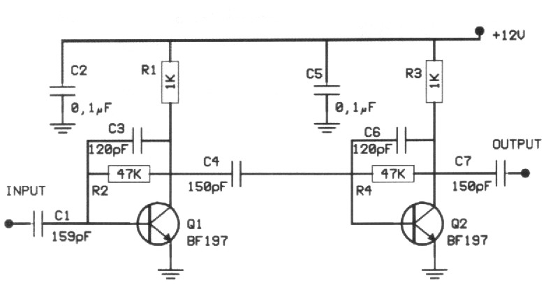
Many times we needed to strengthen a small signal in the region of VHF or FM. The preamplifier that we propose offers 20dB in all the region of VHF and it still can reach also their 500MHz. The amplifier...
The low-frequency signal generating circuit demonstrates excellent performance characterized by stable operation, high output power, and minimal waveform distortion. It serves as an ideal source for low-frequency measurement signals. The circuit includes an operational amplifier (A) with a feedback...