Monostable-multivibrator

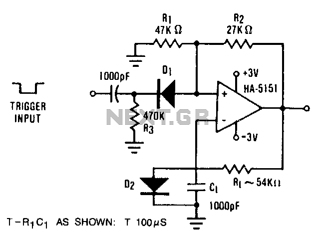
The circuit demonstrates the functionality of the HA-5151 as a battery-powered monostable multivibrator. In this configuration, the time constant is set to 0.632, simplifying the time constant equation to T = R1 * C1. Diode D2 is employed to ensure the output remains in a defined state by clamping the negative input to +0.6 V. The triggering mechanism is established using capacitor C1, resistor R3, and diode D2. An applied trigger voltage lowers the positive input beneath the clamp voltage of +0.6 V, resulting in a change of the output state. This output state is maintained because the negative input cannot adjust to the change due to the presence of resistors R and C. The circuit is designed to produce an output pulse width of approximately 100 microseconds. Utilizing potentiometers for R1 and variable capacitors for C1 enables a broad range of adjustments in the time constant T.
The circuit utilizing the HA-5151 as a monostable multivibrator operates under the principle of generating a single output pulse in response to a triggering input. The HA-5151 is a precision operational amplifier that can function effectively in low-power applications, making it suitable for battery-powered designs. The time constant, defined by the product of the resistance R1 and capacitance C1, dictates the duration of the output pulse.
In this configuration, the diode D2 is crucial for establishing a stable reference point for the negative input, ensuring that it is clamped to +0.6 V. This clamping action prevents unintended fluctuations in the output state, enhancing the circuit's reliability. The triggering process relies on the interaction between the capacitor C1, resistor R3, and diode D2. When a trigger signal is applied, it pulls the positive input below the defined clamp voltage, prompting the output to transition to its active state.
The design allows for flexibility in tuning the output pulse width through the use of adjustable components. By incorporating potentiometers for R1 and variable capacitors for C1, the circuit can accommodate a wide range of applications, from precise timing functions to broader timing intervals. The output pulse width, fixed at approximately 100 microseconds in the original configuration, can be modified based on the selected values of R1 and C1, thereby providing versatility for various electronic applications.
Overall, this circuit exemplifies the practical use of the HA-5151 in creating reliable timing circuits, with the ability to adjust parameters as needed for specific requirements in electronic design.The circuit illustrates the usefulness of the HA-5151 as a battery-powered monostable. In this circuit, the ratio is set to .632, which allows the time constant equation to be reduced to: T=R1*C1. D2 is used to force the output to a defined state by clamping the negative input at +0.6 V. Triggering is set by C1, R3, and D2. An applied trigger pulls the positive input below the clamp voltage, +0.6 V, which causes the output to change state. This state is held because the negative input cannot follow the change because of R,. C,. This particular circuit has an output pulse width set at approximately 100 us. Use of potentiometers for R1 and variable capacitors for C, will allow for a wide variation in T.