
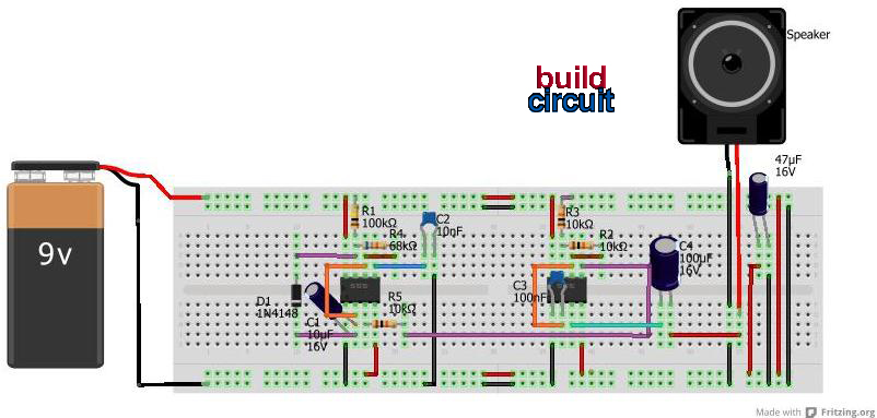
Motion Sensor Switch for Light

The described circuit integrates a Passive Infrared (PIR) sensor module, which is critical for detecting motion within a specified radius. The sensor is mounted at a height of 3 meters, optimizing its field of view to cover an area of approximately 10 meters in radius. The connection of the PIR module to the main circuit is facilitated through a 4-core screened cable, which minimizes interference and ensures stable communication between components.
Powering the circuit is achieved through a regulated 12V DC power supply, which can either be sourced from a conventional adapter or a solar power box, providing flexibility in installation locations. The PIR sensor's relay output is designed to toggle upon detecting movement, which triggers the MOSFET (T1) to activate. Resistor R1 serves as a current-limiting component, ensuring that T1 operates within safe parameters.
Upon activation of T1, the electromagnetic relay (RLY1) is energized, allowing current to flow to the electric sprinkler system. This relay serves as a control mechanism, enabling the sprinkler to operate only when movement is detected, thus conserving water and energy. The circuit design also incorporates spare contacts on RLY1, which can be utilized for additional functionalities, such as activating a high-power warning alarm, enhancing the system's overall utility.
T1 is configured as a mini electronic timer, which provides a delay feature. This means that even after the PIR sensor no longer detects motion and its relay output turns off, the output relay (RLY1) remains activated for a short duration. This delay is adjustable and is determined by the timing capacitor (C2), allowing customization of the system's response time to suit specific operational requirements. This feature can be particularly beneficial in applications where a sustained operation is necessary after initial activation, such as allowing the sprinkler to complete its cycle before shutting off.Install the PIR module hanging from a 3 metre high mast (to cover 10 metre radius area) and connect its supply and relay terminals to our finished and enclosed circuit, observing right polarity. A 4-core screened cable can be used for this interconnection. Power the circuit from a regulated 12VDC adaptor/solar power box. Whenever the PIR module detect movement of a live body its relay output toggles and the switching mosfet (T1) in the circuit is switched to on via resistor R1 and related parts. As as result, the EM relay at the output of T1 is activated and the electric sprinkler gets its supply through the relay (RLY1) contacts.
This contacts (or spare contacts) can also be used to activate a high-power warning alarm. Please note that, here T1 is wired as a mini electronic timer. Even after the PIR relay switched off, output relay (RLY1) remains in on state for a short duration decided by the value of timing capacitor C2. 🔗 External reference
Related Circuits
This project involves a simple light-activated police siren utilizing a light-dependent resistor (LDR) and an NE555 timer. It is advisable to complete some preliminary projects before attempting this one. The NE555 timer, configured in slow astable mode with a...

The chosen Hall Effect sensor is the AH180 Micropower Omnipolar Hall-Effect Sensor Switch. This sensor is utilized to detect the removal of a cup. The operational principle of the Hall Effect sensor involves outputting a high or low signal...
The wireless remote control transmitter circuit consists of control buttons S1 to S16, resistors R1 to R3, a capacitor C1, a regulator diode VS, a crystal oscillator BC1, and DTMF encoder integrated circuits IC1 and IC2. The circuit components...

A magnet is positioned on the door, while a magnetic reed switch is installed on the door casing. When the door is closed, the circuit is disabled. When the door is opened, the circuit becomes active. In this circuit design,...

An automatic emergency lighting circuit is presented, suitable for self-installation in households. It utilizes smaller components, resulting in a lower cost. Under normal conditions, the 220V AC mains voltage is reduced by capacitor C1, and then processed through a...

The microcontroller program is designed to support two communication protocols: the one-wire bus utilized by the DS1820 temperature sensor and the serial protocol used for communication with a computer. Upon power-up, the program retrieves data from the temperature sensors...