
Motional feed back amplifier
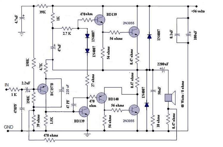
This amplifier circuit employs a feedback mechanism that utilizes the current flowing through the speaker's voice coil to enhance audio fidelity. By achieving a more accurate representation of the cone's movement, the circuit effectively reduces distortion that typically arises from the nonlinearity of dynamic loudspeakers, especially at low frequencies where the cone excursions are significant. The design's reliance on a single power supply simplifies the implementation, making it suitable for various audio applications without the need for complex power management.
The Class B output stage configuration allows for efficient operation, with the 2N3055 transistor providing the necessary power amplification. The inclusion of a pre-driver and driver stage ensures that the signal is adequately amplified before reaching the output stage, maintaining clarity and reducing the risk of distortion. The feedback loop, utilizing a 0.47-ohm resistor, plays a crucial role in monitoring the speaker's performance, allowing for real-time adjustments to the amplifier's output based on the speaker's behavior.
The adjustable half supply at the speaker coupling capacitor provides flexibility in tuning the amplifier's response, enabling the user to optimize performance for different speaker configurations. Additionally, the capability to adjust the quiescent current through the output transistors allows for precise control over the amplifier's thermal performance and efficiency, ensuring reliable operation over extended periods.
Overall, this amplifier circuit represents an innovative approach to audio amplification, combining established principles of feedback with modern design practices to deliver high-quality sound reproduction. Its versatility and adaptability make it suitable for a wide range of audio systems, from home theaters to professional audio setups.This versatile amplifier circuit is designed and submitted by Mr Seetharaman Subramanian from Chennai. The full credit of this article goes to him and we are very proud to publish this fabulous circuit here.
This concept has appeared long back in Practical Electronics a UK based Magazine. Based on this concept I designed this circuit during 1981 to 1986 with lots of field trials and modifications, the design was frozen in 1986. I have assembled so many amplifiers for me and for my friends based on this design with various power levels. They are still kicking in so many houses. This concept can be applied to any existing amplifier also. You must listen to believe the crystal clear thumping bass response. crystal clear mid and hi frequencies. Good transient response with very low distortion. Hope you guys will enjoy the reproduction of this amplifier. In the art of audio sound reproduction it is well-known that the dynamic loudspeaker is more nonlinear and generates more distortion than all the other system components combined.
This is particularly true at low frequencies which require large cone excursions where the stiffness of both the inner spider and the outer surround increases rapidly as the cone approaches its peak displacement, resulting in a nonlinear suspension compliance generating high distortion. For example, in a typical high fidelity sound system at a frequency of about 35 Hz the total harmonic distortion of the amplifier might be of the order of 0.
01%, whereas the distortion of the loudspeaker might range from about 3. 0% to about 50. 0%, depending upon the loudness. If this cone motion can be sensed and given as a feed back to the earlier stage of the amplifier, this distortion can be reduced dramatically. Motional Feedback (MFB) was a speaker system developed in the early 1970s by Philips Holland. It introduced a feedback system to the woofers of HiFi loudspeakers, enabling them to achieve a more extended low frequency response in a relatively small enclosure.
The key benefits are a very controlled bass response. Any distortion induced by the enclosure or the woofer itself is immediately corrected by the feedback. These hand-built speakers were sounding very good and were quite expensive. As a different approach, instead of using the cone movement, the current flow through the voice can be sensed (the current is proportional to cone movement) and can be used as a cone movement feedback.
This novel idea is used in this amplifier design (I don`t claim any originality; this idea has appeared in Practical Electronics UK Magazine long back They might have even patented it). The amplifier used here is a standard Philips audio application circuit, with a specification of 40 Watt RMS @ < 0.
06% Total Harmonic Distortion into 8 ohms impedance speaker and having a frequency response from 20Hz to 100 KHz, suitably modified for our application. The amplifier is a conventional class B directly coupled quasi complimentary out put stage, operating with single 56Volt supply (no need for a regulated or dual power supply).
BC157 is the pre-driver and half supply stabilizer. BD 139 is the driver, a BD139 and a BD140 complimentary pair out put driver stage with 2N3055 as final out put stage. The speaker voice coil current is sensed through 0. 47 ohms resistance connected from speaker one end to ground. This signal is given as negative fed back to previous stage through 470 ohms. The half supply at speaker coupling capacitor can be adjusted by varying the 39K resistance (if required you may fix a 100K pre set in the place of 39K and adjust for half supply with no in put signal at junction of both 0.
47 ohms of out put transistors and speaker coupling capacitor). The quiescent current through output transistors can be adjusted with 22 ohms in series with two bias diodes 1N4007. The value for 50mA quiescent current will lie between 15 to 33 ohms for a supply of 56volts 🔗 External reference
Related Circuits
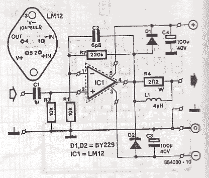
The LM12 operational amplifier can output currents up to 10A. The LM12 is encapsulated in a TO-3 package with 4 pins, can support up to 800W, and has sufficient internal protection. The LM12 operational amplifier is designed for high-current applications,...
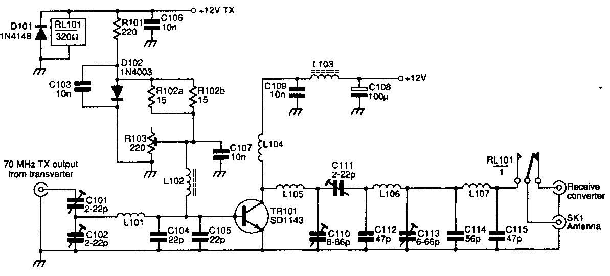
This 70 MHz RF power amplifier circuit utilizes the SD1143 transistor, which offers a gain of approximately 14 dB in this configuration. The design leverages the characteristics of a 175 MHz device. The RF power amplifier circuit designed around the...
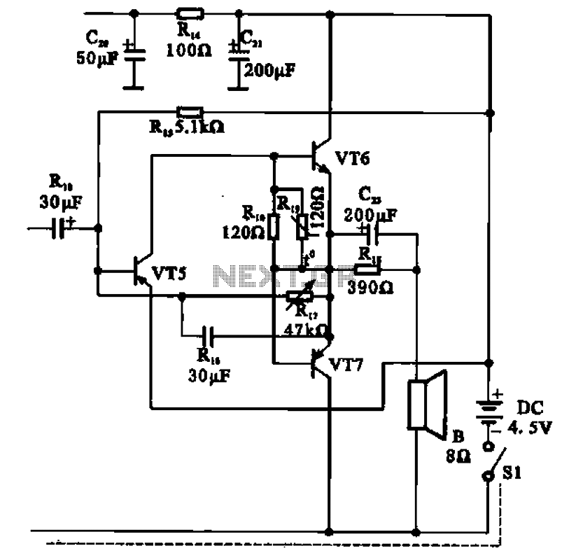
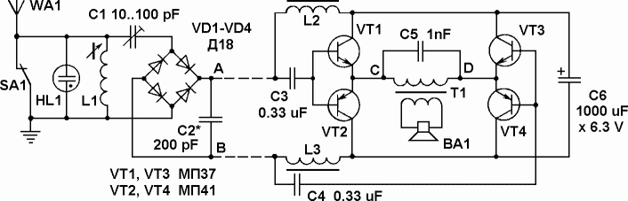
The transistor radio features a common output transformerless (OTL) power amplifier circuit. The VT5 component serves as the bias resistor for the driver stage. VT6 and VT7 form a complementary symmetry configuration, with VT6 being a germanium NPN transistor...
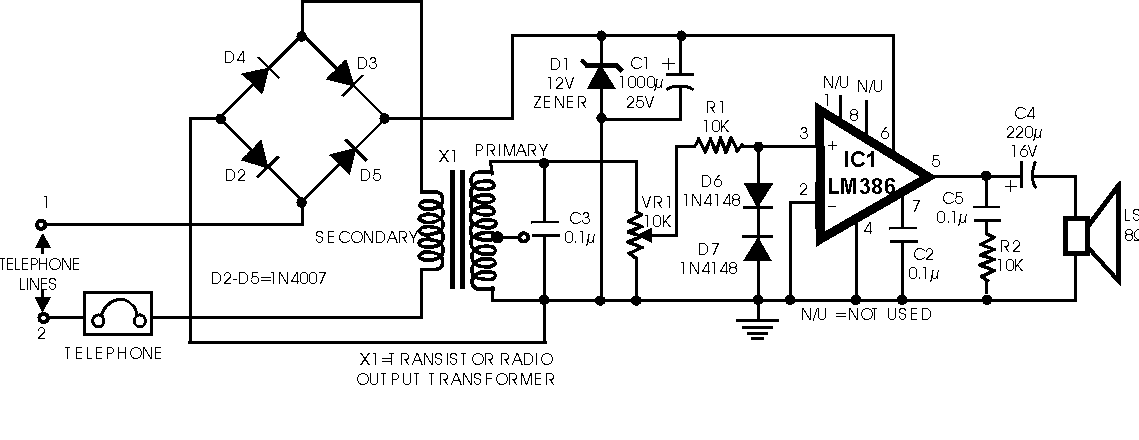
During a telephone conversation with a distant subscriber, it is common to experience frustration due to the faintness of the voice, making it difficult to understand. To address this issue, a circuit for an inexpensive amplifier is presented. This...
During experiments with various receivers and amplifiers powered by "free energy," it was discovered that connecting the audio amplifier to the receiver using only two wires for audio signals and supply voltage is more convenient. This setup allows the...
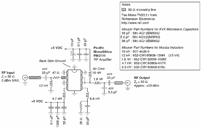
RF Power Amplifier 1 Watt. Jams Cellular Downlink Band: 800-950 MHz. The RF power amplifier described is designed to operate within the cellular downlink frequency range of 800 to 950 MHz, delivering an output power of 1 Watt. Such amplifiers...