
motor controller
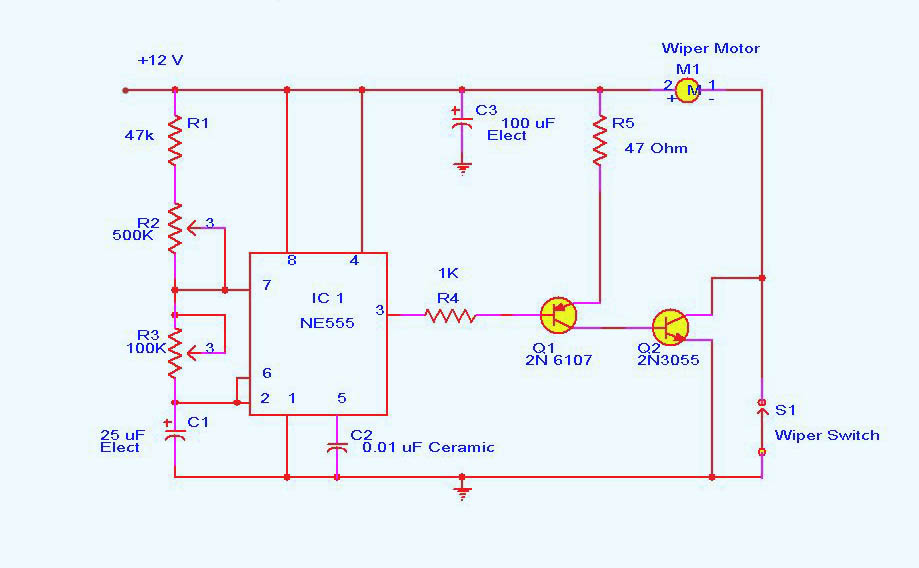
An automatic wiper control circuit is also described, which addresses the inconvenience of continuously operating wipers during light rain. This control circuit enables the wiper to operate at intervals ranging from 1 to 10 seconds. It is constructed around an astable multivibrator using the NE555 timer. The output at pin 3 remains high for a duration determined by resistor R2 and low for a duration set by resistor R3. The low output pulse activates a transistor pair that drives the wiper motor, completing one sweeping cycle before waiting for the next low pulse to initiate the subsequent sweep.
The DC motor control circuit utilizing the NE555 timer is an effective implementation of PWM for speed regulation. The circuit's design leverages the CD40106B IC, which is known for its reliability in generating stable pulse signals. The astable multivibrator configuration allows for continuous pulse generation, which is crucial for controlling the motor speed. By adjusting the duty cycle through resistor R2, the effective voltage supplied to the motor can be modulated, providing precise control over its speed.
In the automatic wiper control circuit, the NE555 timer operates in astable mode, producing a square wave output. The timing components, R2 and R3, are critical in determining the frequency of the output signal, thereby controlling the wiper's operation cycle. The integration of transistors to drive the motor ensures that the circuit can handle the current requirements of the wiper motor, making it suitable for automotive applications. This design exemplifies the versatility of the NE555 timer in practical electronic applications, particularly in motor control scenarios.DC motor control circuit using NE555 Are you familiar with all the applications of 555 timer circuits If not, we can help you. We all know that for better understanding, the best source is an authenticated book on the subject. CircuitsToday presents an online store which has reviews on 3 books that are considered to be the best in providing the b
asics and applications of the 555 timer IC. We have reviewed them in detail. You check them out and buy them here:-3 Great Books to Learn 555 Timer Circuits and Projects. A simple DC motor controller circuit using PWM Motor Speed Control Description Here is a simple PWM motor speed controller circuit that can be used for varying the speed of low power DC motors. The variation in speed is achieved by varying the duty cycle of the pulse supplied to drive the motor.
Of the two gates of IC CD40106B, N1 is wired as an inverting Schmitt Trigger astable multi vibrator for producing pulses and N2 as an inverting buffer to drive the transistor during positive cycles at base. The duty cycle is set from resistor R2. R1 limits the base current of transistor SL Automatic Wiper Control Description A continuously working wiper is a big problem when it is raining slightly.
The wiper control given here makes the wiper to sweep at rates from 1S to 10 S. The circuit is build around an astable multivibrator using NE 555. Here the output at pin 3 remains high for a time period set by R2, and low for a time period set by R3. The low output pulse drives the transistor pair to drive the wiper motor to make one sweeping cycle and waits for next low pulse to arrive for next sweep.
The high going pulse at pin 🔗 External reference
Related Circuits
This ISP Programmer can be utilized for in-system programming or as a standalone SPI programmer for Atmel ISP programmable devices. The programming interface is compatible with STK200 ISP programmer hardware, allowing users of STK200 to also use the software...
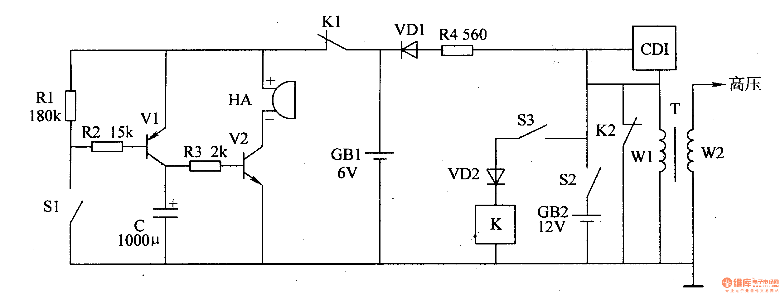
The motorcycle anti-theft alarm circuit consists of a detection alarm circuit, a charging circuit, and an anti-theft control circuit, as illustrated in figure 7-94. The detection alarm circuit includes a mercury switch (S1), resistors (R1-R3), a capacitor (C), transistors...
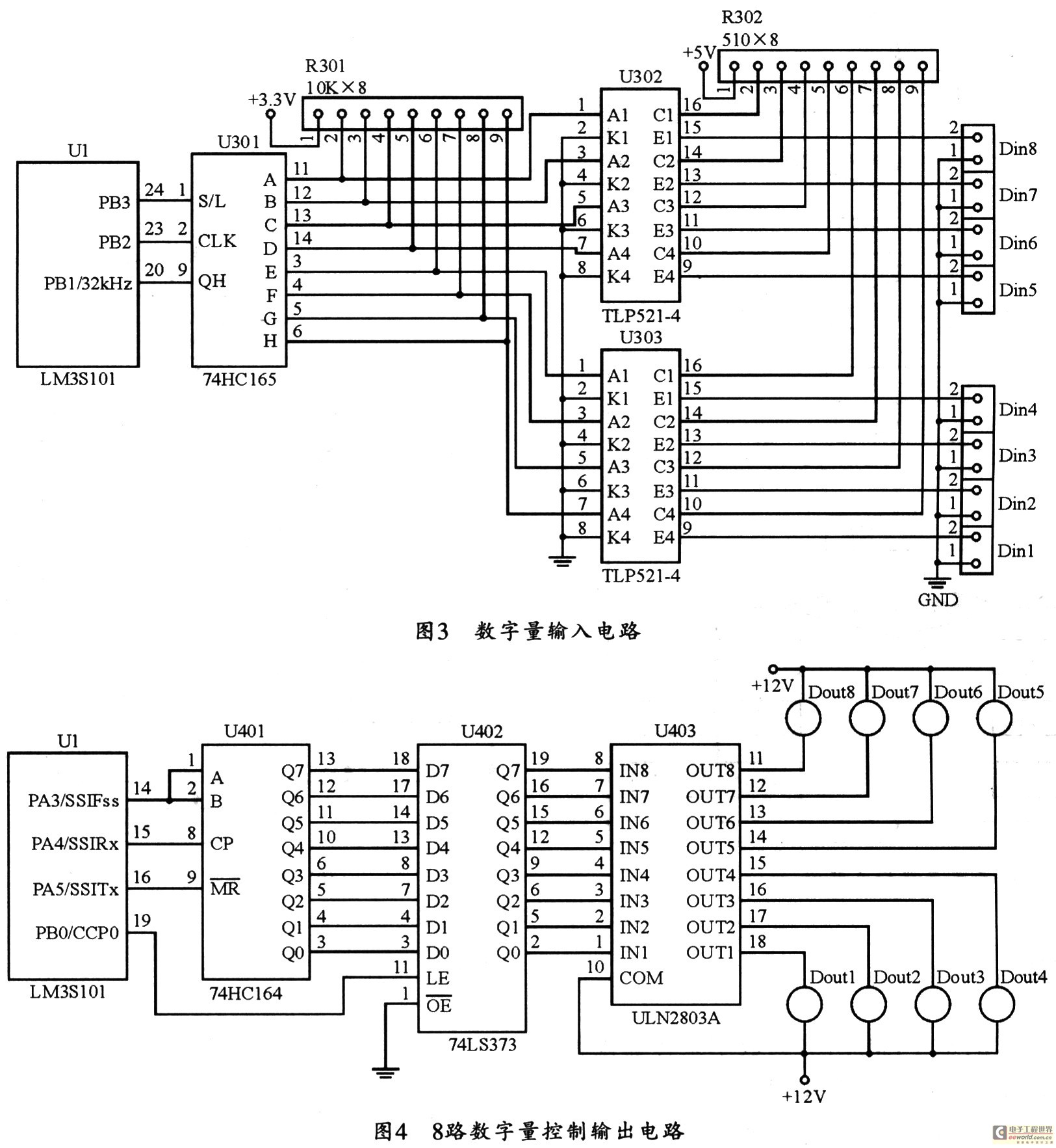
The figure utilizes a controller as the primary equipment for gathering and controlling digital data within an on-site monitoring system. The stability of on-site control operations is crucial to the overall system performance. Therefore, a simple and stable structure...
The AVR 8-Bit RISC microcontroller from Atmel is a widely used microcontroller. This microcontroller integrates EEPROM, RAM, an Analog to Digital converter, numerous digital input and output lines, timers, UART for RS-232 communication, and various other features. An article...

The TPS6420x controller is designed to operate from one to three series-connected cells or from a 3.3 V or 5 V supply obtained from a USB port. At its output, it can produce 3.3 V at 2 A, suitable...

A simple frequency meter or frequency counter circuit featuring an LCD display and an AVR microcontroller. This includes a DIY schematic circuit diagram and embedded C code. The frequency meter circuit is designed to measure the frequency of input signals...