
mp3-player-booster-circuits.html
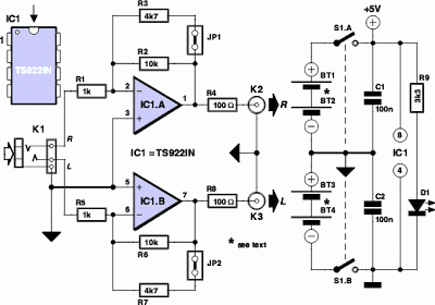
MP3 players are very popular today, especially the smaller memory-stick formats that are easy to transport, allowing for personal sound systems on the go. However, when sharing music with others, these players often lack sufficient power. The MP3 booster addresses this issue, functioning as an amplifier that connects directly to a Hi-Fi system. This enables users to invite friends to share music at gatherings. The small, battery-powered players typically provide an output signal adequate for 32 Ohm headphones, with an output of 1mW capable of producing sound pressure levels (SPL) up to 90 dB, which can cause hearing damage after prolonged exposure. The maximum output voltage is around 200mV, insufficient for driving a power amplifier that usually requires 1V for optimal performance. Thus, an additional circuit to boost the output voltage is necessary. The design incorporates two gain settings: three times and ten times, utilizing amplifiers IC1A and IC1B from a single TS922IN package. The MP3 player's output is connected to the amplifier inputs through a stereo cable and socket K1. The gain is determined by the relationship between resistors R2 and R1 (and R6 and R5 for the other channel). A jumper (JP1 or JP2) allows for adjusting the gain by connecting resistor R3 (or R7) in parallel with the feedback resistor, reducing the gain to approximately three. The amplified signal is then routed to output sockets K2 and K3 via resistors R4 and R8, which help maintain stability against parasitic capacitance from long output cables. The TS922IN op-amp is preferred for its low supply voltage operation (maximum 12V) and reasonable output current (80mA max). The circuit is powered by rechargeable batteries (NiCd or NiMH) with a supply voltage of 5V, achievable with four batteries, or alternatively by four non-rechargeable batteries (6V), which is safe for the circuit. A symmetrical supply configuration is implemented using two battery holders with two AA cells each connected in series. A double pole switch (S1A/B) controls the power supply. If the TS922IN op-amp is unavailable, standard op-amps like the NE5532, TL082, or TL072 can be used, but they require a higher supply voltage. Care should be taken when connecting the circuit to a power amplifier to avoid overloading it, as the output signal can be significantly larger. The circuit uses a stereo jack socket for the input and phono sockets for the output, ensuring compatibility with MP3 players and power amplifiers. Alternatively, shielded cables can be soldered directly to the circuit for convenience.
The MP3 booster circuit is designed to enhance the audio output from portable MP3 players, enabling a more robust audio experience when connecting to external sound systems. The circuit's core consists of two operational amplifiers configured in a non-inverting amplifier configuration to achieve the desired gain settings. The choice of the TS922IN op-amp is significant due to its capability to function efficiently at low voltages, making it suitable for battery-powered applications.
The input stage of the circuit is connected through a stereo cable to the MP3 player's output, ensuring a clean audio signal is received. The gain selection mechanism, utilizing jumpers and resistors, allows users to adjust the amplification based on the audio source's volume and quality. This flexibility is crucial for accommodating various music genres and recording levels.
The output stage employs resistors R4 and R8, which serve dual purposes: they help mitigate the effects of parasitic capacitance that can lead to oscillation and instability in the amplifier's performance, and they provide a level of short-circuit protection for the booster. This ensures that the circuit can handle different cable lengths and types without compromising audio quality.
Powering the circuit with rechargeable batteries not only enhances portability but also aligns with environmentally friendly practices. The inclusion of a double pole switch allows for easy operation, enabling users to turn the entire circuit on or off without needing to disconnect the batteries.
Overall, the MP3 booster circuit is a practical solution for enhancing the audio output of MP3 players, making it suitable for social gatherings and ensuring that music can be enjoyed at higher volumes without distortion or damage to connected equipment. The design emphasizes simplicity, efficiency, and user-friendliness, making it accessible for both novice and experienced electronics enthusiasts.MP3 players are all the rage these days. The smaller ones in memory-stick format are particularly easy to take with you; your very own personal sound system` on the move! It`s when you want others to share your taste in music that you ¬nd these players to have a lack of power.
You can get round this problem with the help of the MP3 booster, a sm all amplifier that can be used to connect your MP3 player directly to your Hi-Fi. When you next invite your friends to a party you can ask them to bring their personal music` as well as the usual drinks! But ¬rst we have to build this booster! The small battery-powered players have an output signal that is more than suf ¬cient to drive a set of 32 Ohm headphones.
You`ll often ¬nd that with an output of 1mW the sound pressure level (SPL) produced can reach up to 90 dB. This would be suf ¬cient to cause permanent damage to your hearing after only one hour! The maximum output voltage will then be around 200mV. This, however, is insuf ¬cient to fully drive a power amplifier. For this you`ll need an extra circuit that boosts the output voltage. Power amps usually require 1 V for maximum output, hence the signal has to be ampli ¬ed by a factor of ¬ve.
We will also have to bear in mind that quieter recordings may need to be ampli ¬ed even more. We`ve used a simple method here to select the gain, which avoids the use of potentiometers. After all, the MP3 player already has its own volume control. We decided to have two gain settings on the booster, one of three times and the other ten times. Ampli ¬ers IC1A and IC1B (for the right and left channels) are housed in a single package, a TS922IN. The output signal of the MP3 player is fed via a stereo cable and socket K1 to the inputs of the amplifiers.
The gain depends on the relationship between resistors R2 and R1 (R6 and R5 for the other channel) and is equal to ten times. When you add jumper JP1 (JP2), resistor R3 (R7) will be connected in parallel with the negative feedback resistor R1 (R6), which causes the gain to be reduced to about three.
When you start using the booster you can decide which gain setting works best for you. Resistor R4 (R8) takes the ampli ¬ed MP3 signal to the output socket K2 (K3). A cable then connects these phono sockets to the input of your power amplifier. The resistors connected in series with the output (R4 and R8) are there to keep the booster stable when a long cable is connected to its output. Cables have an unwelcome, parasitic capacitance. This capacitive effect could (due to phase shifts of the signal) affect the negative feedback of the booster in such a way that a positive feed back occurs, with the result that the booster oscillates and possibly damages the power amplifier!
The resistors (R4 and R8) effectively isolate the output of the booster from the parasitic capacitance of the output cable. They also protect the booster outputs from short circuits. We`ve used a TS922IN opamp in this booster because it can operate at very low supply voltages (the maximum is only 12 V!), but can still output a reasonable current (80 mA max.
). For the supply we`ve used rechargeable batteries (e. g. NiCd or NiMH cells) so that we don`t need a mains supply. To keep the number of cells required as small as possible, we`ve chosen a supply voltage of 5 volt; this can be supplied by four rechargeable batteries. It is also possible to use four ordinary, non-rechargeable batteries; it`s true that the supply voltage then becomes a bit higher (6 Volts), but that won`t cause any harm.
Since we`ve used a symmetrical supply for the booster (2 x 2 batteries), it will be easiest if you use two separate battery holders, each with two AA cells. The two holders are connected in series. Make sure that the batteries are connected the right way round; the positive of one always has to be connected to the negative of the next.
This also applies to the connection between the two battery holders. S1A/B is a double pole switch, which is used to turn both halves of the battery supply on or off simultaneously. If you can`t ¬nd the (dual) opamp we`ve used (or an equivalent), you could always use standard opamps such as the NE5532, TL082 or TL072.
These do need a higher supply voltage to operate properly. In these cases you should use two 9 V batteries and replace resistor R9 with a 15 k © one. Do take care when you connect the circuit to your power amplifier because the output signal can be a lot larger and you could overload the power amplifier. (Although you`re more likely to damage the loudspeakers, rather than the amplifier!) (Please note that these two 9 V batteries can`t be used as a supply for the TS922IN!) In our circuit we`ve used a stereo jack socket for the input and phono sockets for the output because these are the most compatible with MP3 players and power amplifiers respectively.
If you wanted to, you could solder shielded cables directly to the circuit instead, with the correct plugs on the ends. You`ll never ¬nd yourself without the correct connection leads in that case! You are reading the article about MP3 Player Booster Circuits and you can find articles MP3 Player Booster Circuits this the url.
You may distribute or copy articles MP3 Player Booster Circuits this is beneficial if you or your friends, but do not forget to include the link source. 🔗 External reference