
Multi-point control corridor lights circuit
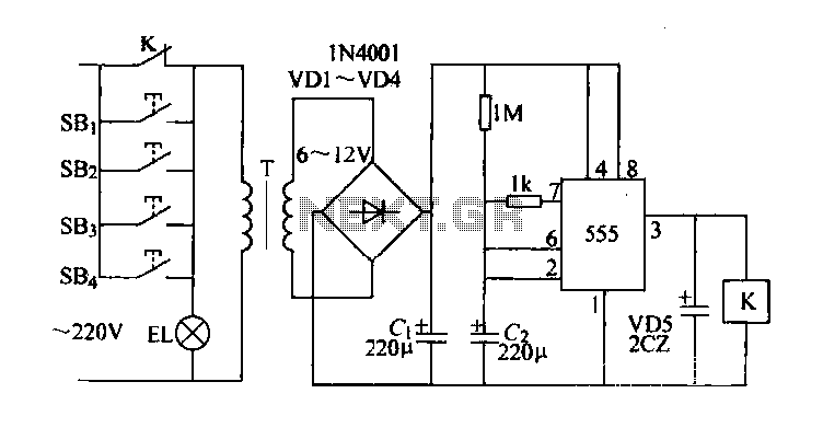
The described circuit employs a 555 timer IC configured in monostable mode to control the lighting system with a self-timer functionality. The control buttons SB1 through SB4 serve as momentary switches that trigger the circuit. When any button is pressed, it sends a signal to the 555 timer, initiating the timing sequence.
The transformer and rectifier convert the AC supply voltage into a suitable DC voltage for the circuit. The 220µF capacitor acts as a timing element, determining the duration for which the lights remain on after the button is released. The timing period is defined by the formula T = 1.1 * R * C, where R is the resistance in ohms connected to the timing circuit and C is the capacitance in farads. In this case, the capacitor is pre-charged to zero volts, and as the capacitor charges, the voltage across it rises until it reaches approximately 2/3 of the supply voltage, at which point the 555 timer output transitions low.
Relay K plays a crucial role in controlling the power to the EL horse lights. Its normally open contact allows current to flow to the lights when the relay is activated, turning them on. Once the timing period elapses, the relay deactivates, interrupting the power supply to the lights, which subsequently turn off.
This circuit design allows for flexible placement of control buttons throughout a corridor, enhancing user convenience while ensuring that the lighting system operates efficiently. The use of a 555 timer IC provides reliable timing control, making the circuit suitable for various applications where temporary lighting activation is desired.Control button switches SB1-SB4 can be installed in different positions corridor, just move SB1 ~ SB4 any one button, lights EL horse lights on, and after decompression transfo rmer, rectifier, to supply the integrated circuit 555. 555 integrated circuits, feet have connected 220yF initial capacitor voltage is zero, in an integrated circuit 555 is the first feet high output, relay K puff actuated, the normally open contact K is closed, the entire circuit into the timing of the self-locking status. Since then the power of the first integrated circuit 555, feet charge the capacitor voltage rises. When the electric charge container about 2/3 of the DC supply voltage to the timing between, about 3min.
In this case 555 integrated circuits pin output toggles low, so K release, contact switch K automatically disconnected, lamp EL off. Just then press SB1-SB4 any of a button, the forks will re-timing lights turned on.
Related Circuits
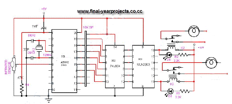
This is a comprehensive electrical project report on an Infrared Remote Control On/Off Switch, submitted to fulfill the requirements for the Bachelor of Engineering degree in Electrical Engineering. The project is designed to control the operation of home appliances...
Figure 2-33 (a) illustrates the schematic diagram of a robot approaching an object. When no objects are detected in front of the robot, it moves forward in a straight line. If an object is detected on the left or...
When the circuit is initially powered, neither transistor is activated, resulting in high base voltages for both and a tendency to turn on. Due to slight asymmetries, one transistor will activate first, leading the circuit into one of its...

This is a design circuit for a low-cost FM antenna booster that can be used to listen to programs from distant FM stations clearly. The antenna FM booster circuit comprises a common-emitter tuned RF preamplifier wired around the VHF/UHF...
This example presents a switch DC regulated power supply circuit designed for buck-mode +5V applications. It consists of a power supply circuit, an impulsator, a voltage sampling or pulse width modulation circuit, and a buffering driver circuit, as illustrated...
This design is for an interpolating scanner, a circuit featuring multiple signal inputs, a control voltage input, and a signal output. The output selectively transitions between inputs, smoothly fading from one to the next as the control voltage increases....