
Multiple Capacitor Charger
L1 and L2 are bifilar wound coils around the same toroidal core, as illustrated in Figure 2. Each coil consists of approximately 25 turns. L1 is constructed using 0.5 mm wire, while L2 is made with a thinner wire. When the number of turns was reduced to around 16, it was observed that the capacitors charged to similar voltages, and the supply current increased to approximately 560 mA from the previous 320 mA. This indicates that a lower inductance results in higher current draw, although the inductive kickback (IKB) voltage remains approximately constant for that number of turns. The IKB across L1 and L2 is presented in Figures 3(a) and 3(b). Capacitors C3 and C4 are charged to 240 VDC and 220 VDC, respectively, through 1N4007 diodes due to this effect, as shown in Figure 3(c).
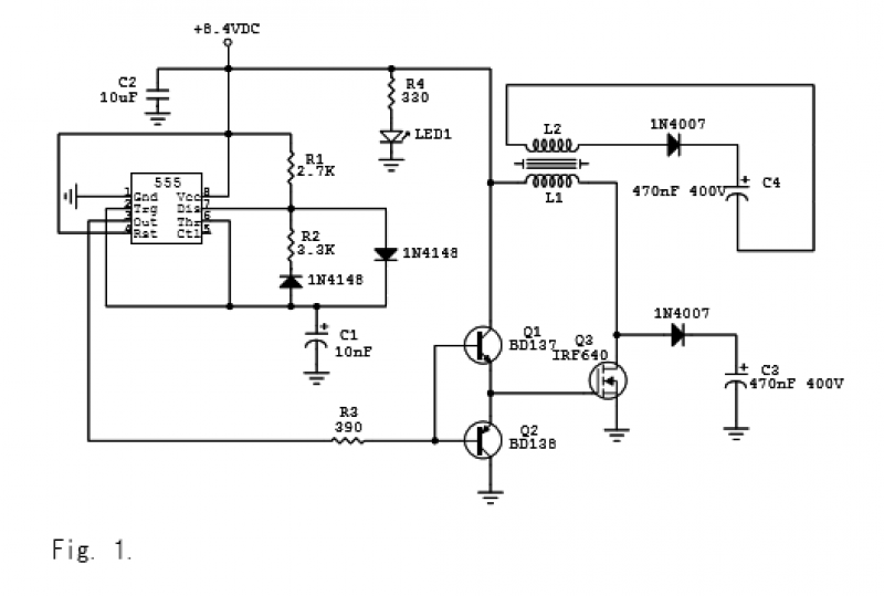
The circuit utilizes a 555 timer IC configured in astable mode to generate a square wave output. The timing components R1, R2, and C1 determine the frequency of oscillation. The bifilar coils, L1 and L2, are critical in the charging process, as they create a magnetic field that facilitates energy transfer to the capacitors. The choice of wire gauge for the coils influences the resistance and inductance, which in turn affects the circuit's performance.
When the number of turns is modified, the inductance changes, which directly impacts the current draw from the power supply. A reduction in turns leads to higher current draw due to decreased inductance, demonstrating the relationship between inductance and current in resonant circuits. The IKB observed across the coils is indicative of the energy stored in the magnetic field, which is released when the current flow ceases.
The diodes (1N4007) serve as rectifiers, allowing the capacitors to charge to high voltages while preventing backflow of current. The ability of the circuit to charge capacitors to significant voltages (240 VDC and 220 VDC) showcases its effectiveness in energy storage applications. Overall, the design and operation of this circuit exemplify key principles in electronics, including oscillation, energy transfer, and the behavior of inductive components.The circuit is shown in Figs. 1-2 and tested succesfully. This is a 555 timer IC based charger. The circuit is operated by 8.4VDC. For R1=2.7K, R2=3.3K, and C1=10nF, oscillation frequency is about 25KHz. Measured period is about 40µs when there is no toroid load. In the presence of toroid, period shrinks to about 30µs. So the frequency jumps from 25KHz to 33.33KHz. About 320mA total current is withdrawn from the supply.
L1 and L2 are bifilar wound coils around the same toroidal core as shown in Fig. 2. There are about 25 turns of each coil. L1 is wound using a 0.5mm wire. L2 is a thinner wire.
When I reduced the number of turns to about 16, I observed that the capacitors are charged to the same voltage and the supply current increased to about 560mA from 320mA. So less inductance means higher current, but the inductive kickback (IKB) voltage stays about the same for that number of turns.
IKB across L1 and L2 are shown in Figs. 3(a) and 3(b). Capacitors C3 and C4 are charged to 240VDC and 220VDC through 1N4007 diodes as a result of this effect. This is shown in Fig. 3(c). By 4beowulf7 - [email protected]
Related Circuits
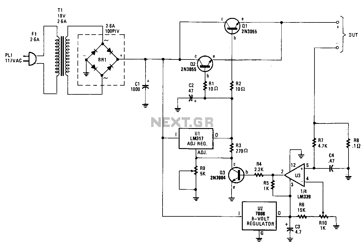
The charger's output voltage is adjustable and regulated, featuring an adjustable constant-current charging circuit that facilitates compatibility with most NiCad batteries. It is capable of charging a single cell or multiple series-connected cells, with a maximum voltage of 18...
When the NiCd charger circuit is connected to the car battery, diode D2 illuminates only if the NiCd battery is connected with the correct polarity. To achieve this, the positive terminal of the NiCd battery is connected to the...
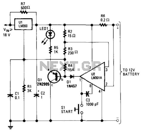
This high-performance charger efficiently charges gelled lead-acid batteries and automatically shuts off upon reaching a full charge. Initially, the charging current is maintained at 2 A; however, as the battery voltage increases, the current gradually decreases. Once the current...
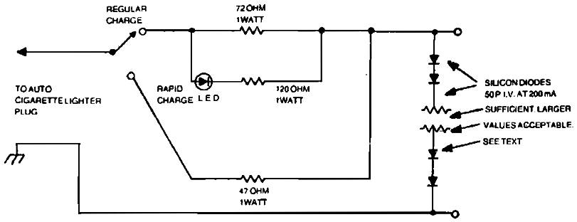
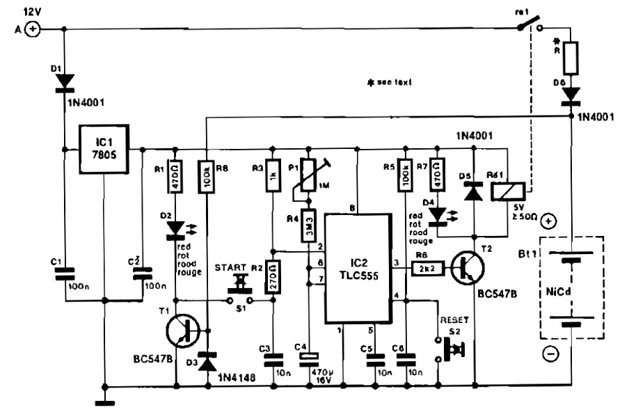
Car charger for NiCd battery packs power supply. This is a car NiCd battery charger circuit that can charge any Ni-Cd battery between 4.8 and 4.4 volts from a classic 12 volts car battery. The charging current is constant...
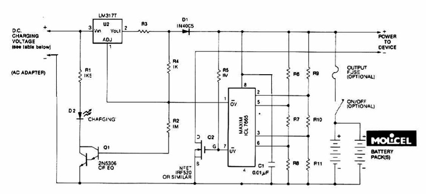
The charging system described is designed for multi-cell lithium battery packs comprising two to six series-connected cells or series/parallel configurations. The schematic diagram originates from the lithium battery charger power supply circuit. This circuit is specifically intended for charging...
A straightforward method for charging a battery using a higher voltage source is illustrated in the accompanying circuit diagram. The circuit requires only one resistor to establish the desired charging current, which can be determined by dividing the voltage...