
Multiple feedback low pass filter
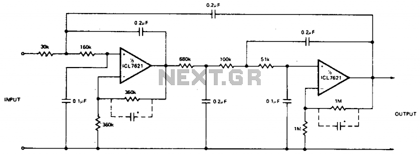
To achieve a low frequency cutoff at 10 Hz while maintaining a voltage gain (AVCL) of 4, a circuit can be designed utilizing operational amplifiers (op-amps) configured in a non-inverting amplifier setup. The low bias currents of the op-amps are essential, as they allow for the use of high resistance values in the feedback network, which in turn minimizes the loading effect on the input signal. This design choice is crucial for applications requiring high input impedance and low output impedance.
The cutoff frequency (fc) is determined by the RC time constant of the circuit, where R represents the resistance and C represents the capacitance. The formula for the cutoff frequency is given by:
fc = 1 / (2πRC)
To achieve a cutoff frequency of 10 Hz, careful selection of R and C values is necessary. For instance, using a resistor of 15.9 kΩ in conjunction with a capacitor of 1 µF would yield a cutoff frequency close to the desired specification.
The passband ripple of 0.1 dB indicates that the circuit should maintain a relatively flat frequency response within the passband, which can be achieved through proper component selection and feedback network design. This ensures that the gain remains consistent across the desired frequency range, enhancing the overall performance of the circuit.
In some configurations, particularly when dealing with high-frequency signals or when stability is a concern, the addition of small capacitors (25-50 pF) may be necessary. These capacitors can help mitigate potential oscillations and improve the phase margin of the circuit, ensuring stable operation across varying conditions. The placement of these capacitors should be strategically considered in the layout to minimize parasitic inductance and capacitance, which could adversely affect the performance of the circuit.
Overall, this configuration is suitable for low-frequency applications where precision and stability are paramount, and the careful selection of components will ensure optimal performance.The low bias currents permit high resistance and low capacitance values to be used to achieve low frequency cutoff. fc = 10 Hz, AVCL = 4, Passband ripple = 0.1 dB. Note that small capacitors (25-50 pF) may be needed for stability in some cases. 🔗 External reference
Related Circuits
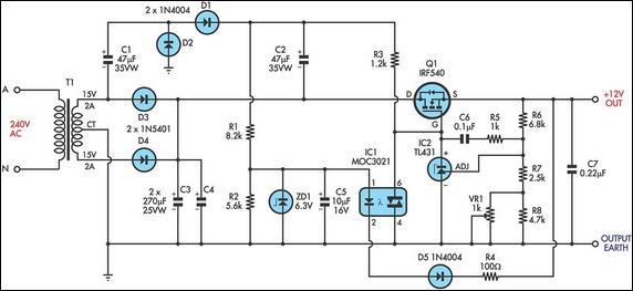
This circuit is a MOSFET-based linear voltage regulator with a voltage drop as low as 60mV at 1A. It utilizes a 15V-0-15V transformer and an IRF540 N-channel MOSFET (Q1) to deliver a regulated 12V output. The required gate drive...
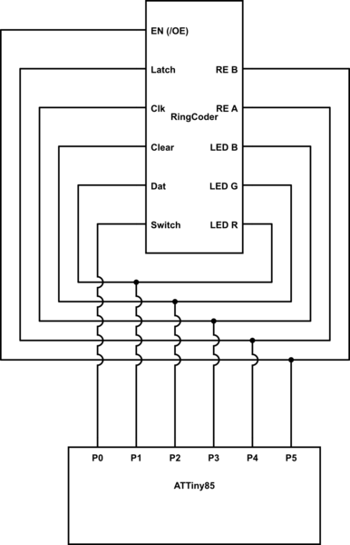
A chip conversion is being performed for the Sparkfun LED RingCoder. The sample code provided with the product functions effectively on an Arduino UNO, utilizing a separate pin for each input/output—specifically, five pins for the shift registers and six...
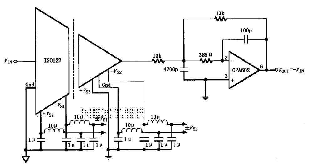
The ISO122/124-type filter circuit is designed to address noise suppression from the DC/DC converter. The internal oscillator frequency of the ISO122/124 modem is set to 500 kHz. The circuit employs inductors and capacitors for filtering to mitigate any beat...
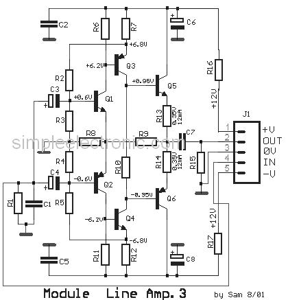
This is a simple low-impedance preamplifier circuit diagram used to amplify an audio signal. The circuit operates with a 12V DC power source and is straightforward due to its minimal component count. The low-impedance preamplifier circuit is designed to enhance...
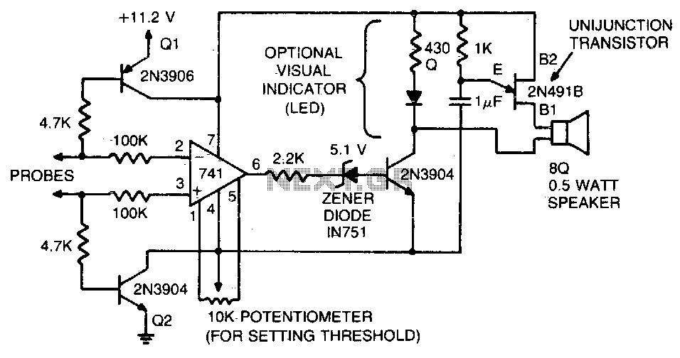
This tester is designed to verify integrated circuit (IC) printed circuit boards. It incorporates two 4 kΩ resistors along with transistors that inhibit current flow through the operational amplifier until the probe circuit is fully established. Additionally, a zener...
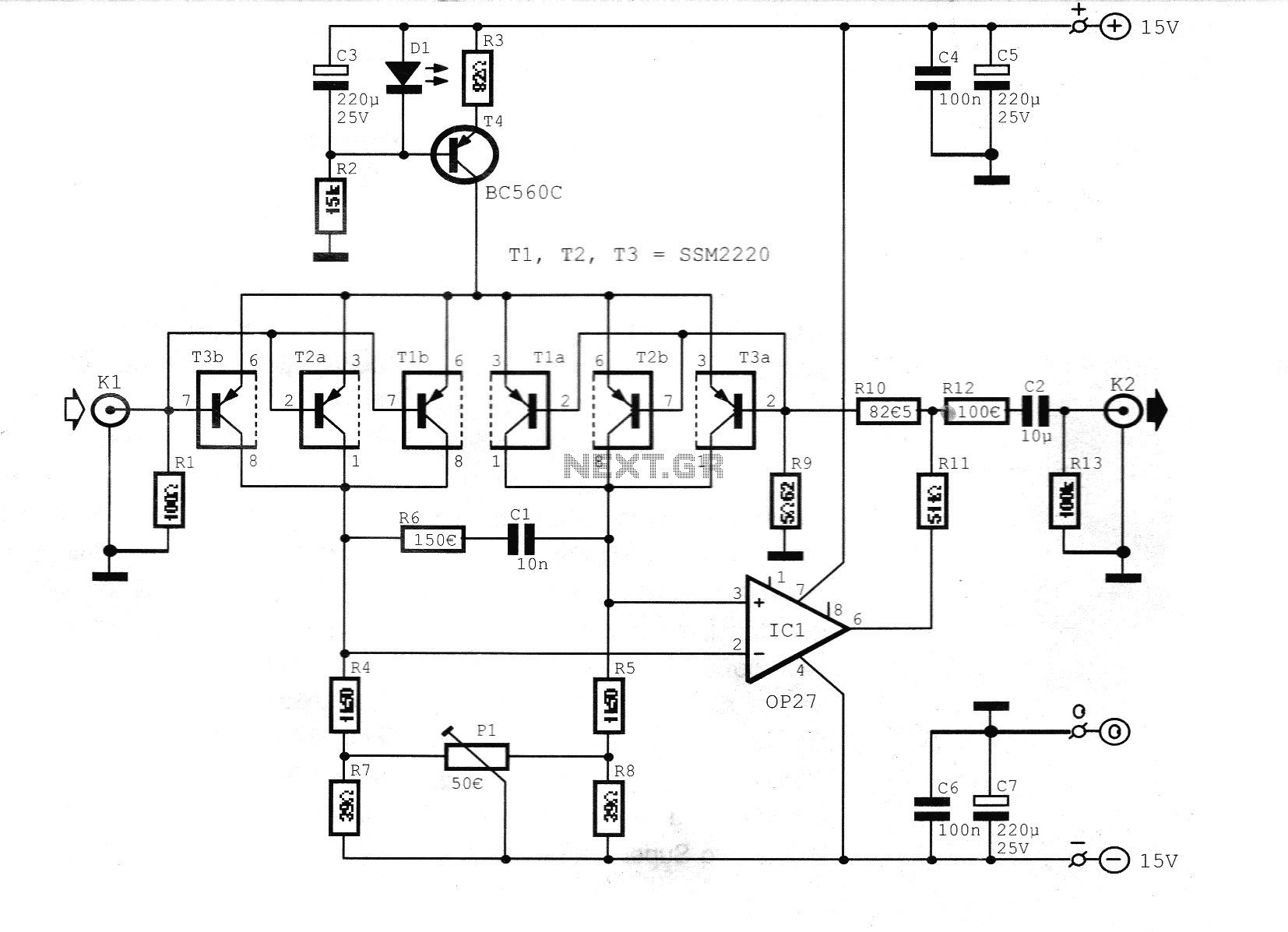
This preamplifier is designed for low-resistance sources such as moving coil heads (MC). The circuit employs three parallel double transistors, SSM2220 or MAT03, which form a differential amplifier that minimizes noise. When connected to an OP27 amplifier, it further...