
Multiplying-converter
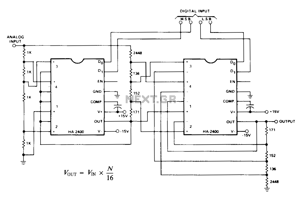
N represents a binary number ranging from 0 to 15, generated by the digital input. When the analog input is set to a fixed DC reference, the circuit functions as a standard 4-bit digital-to-analog converter (DAC), producing an output that is the multiplication of the analog signal and the digital signal. The circuit on the left serves as a programmable attenuator with weight values of 0, 1/4, 1/2, or 3/4. The circuit on the right is a non-inverting adder that combines weights of 0, 1/16, 1/8, or 3/16 to the first output. If four-quadrant multiplication is necessary, a phase selector circuit should be incorporated in series with either the analog input or output. The D0 input of this stage will act as the positive or negative sign bit of the digital input.
The described circuit functions primarily as a digital-to-analog converter (DAC) that translates a 4-bit binary input into a corresponding analog voltage output. The binary input, represented by N (ranging from 0 to 15), is processed to yield an output voltage that is directly proportional to the digital value when the analog input is held at a fixed DC reference.
The programmable attenuator, positioned on the left, allows for variable scaling of the analog signal. It can adjust the output by applying weights of 0, 1/4, 1/2, or 3/4, effectively controlling the amplitude of the analog signal based on the digital input. This feature is essential in applications requiring precise control over signal levels.
On the right, the non-inverting adder circuit combines the output from the programmable attenuator with additional weighted values. The weights of 0, 1/16, 1/8, or 3/16 are added to the output, enabling fine-tuning of the resulting analog signal. This configuration is particularly useful in systems where multiple signals need to be summed together while maintaining signal integrity and ensuring that the output remains non-inverting.
In scenarios where four-quadrant multiplication is desired—allowing for both positive and negative outputs—a phase selector circuit must be integrated. This circuit is positioned in series with either the input or output of the analog section. The D0 input of the phase selector serves as the sign bit, determining whether the output will be positive or negative based on the digital input. This capability expands the functionality of the circuit, making it suitable for a broader range of applications, including those requiring bipolar signal processing.
Overall, the combination of a programmable attenuator, a non-inverting adder, and a phase selector circuit provides a versatile solution for converting digital signals into precise analog outputs while allowing for extensive manipulation of signal characteristics.Where N is the binary number from 0 to 15 formed by the digital input. If the analog input is a fixed de reference, the circuit is a conventional 4-bit D to ac signal, in which case the output is the product of the analog signal and the digital signal. The circuit on the left is a programmable attenuator with weights of 0, 1/4, 1/2, or 3/4. The circuit on the right is a noninverting adder, which adds weights to the first output of 0, 1/16, 1/8, or 3/16.
If four quadrant multiplication is required, place a phase selector circuit in series with either the analog input or output. The D0 input of that stage becomes the + or -sign bit of the digital input. 🔗 External reference