
MUTS Multi-Target Development System
The Multiple Target Development System (MUTS) serves as an efficient platform for developing and testing applications based on Silicon Laboratories microprocessors. The integration of the Target board with the SL Debug Adapter facilitates a streamlined programming process through the SL Integrated Development Environment (IDE), enhancing the user experience during application development. The board's design accommodates multiple microprocessors, allowing flexibility in project specifications and requirements.
The physical layout of the Target board, with its accessible I/O ports and power connections, ensures ease of integration into various project setups. The provision of a reset pin and regulated power supply at 3.3 volts further enhances the board's functionality, making it suitable for a wide range of applications. The inclusion of both C2 programming and serial connection ports allows for versatile communication options, essential for debugging and data transfer during development.
The use of a prototyping board for the test fixture underscores the emphasis on quality and reliability in the verification process. The availability of pre-configured programming files simplifies the testing procedure, allowing developers to quickly assess the functionality of the microprocessor and its associated components. This capability is crucial for ensuring that the system operates as intended before deployment in a final project.
Overall, the MUTS provides a comprehensive solution for developers working with Silicon Laboratories microprocessors, combining ease of use, flexibility, and robust testing capabilities into a single, compact platform.The following describes the design, construction, operation and use of the Multiple Target Developent System (MUTS). The MUTS consists of a Target board (Target) that can connect to a Silicon Laboratories (SL) Debug Adaptor to program the Target board with the SL Integrated Development Environment (IDE).
Thus, the Target can be used as the main pr ocessor in a project but applications can be developed while the Target is connected to the IDE. The MUTS Target board supports several Silicon Laboratories microprocessors with 32-pin LQFP phsical packages and compatible pin configurations such as the C8051F361 and C8051F310. The MUTS Target boards are used in several of our projects. Completed Target boards, populated with a C8051F361 chip, are shown in Photo 1 (above) and in Photo 2.
Photo 1 shows revision 3 of the board which, in addition to the connector for the C2 programming adapter, has a second connector for serial connections. Photo 2 shows revision 2 of the board that has only a connector for a C2 programming adapter on one end of the board.
Revision 3 of the board is now shipped with all Target board orders. The primary use of the Target board is to provide a reasonably small board that can be used to mount the processor chip, regulator, crystal, programming connector and a serial port connector. The board also provides access to all I/O ports, 3. 3 Volt regulated power and the reset pin. Because of its dual-inline physical format, it can be easily plugged into a breadboard socket or plugged into tenth-inch spaced sockets mounted on a perforated project board.
Thus, the Target board provides all of the facilities and connections needed for project development. Photo 3 shows a 361 Target board plugged into a hand-wired test fixture used for in-house verification of finished Target boards.
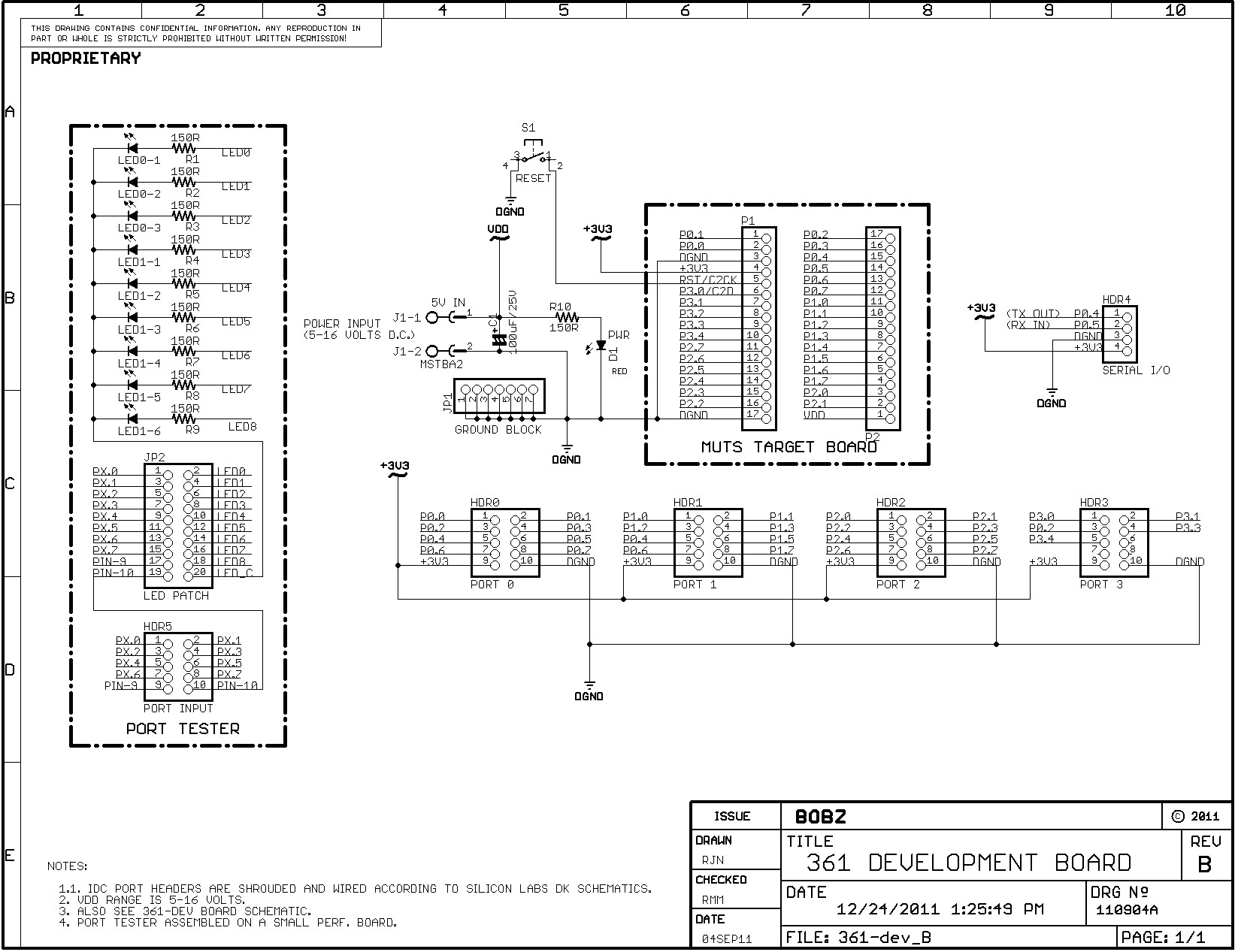
The test fixture is built with a prototyping board available from Parallax, Inc. ®, as noted in the Assembly Guide. These boards, product number 45305, are inexpensive and of high quality. We recommend them for projects that will fit in a 3 by 4 inch format or on a stack of boards of this size. For the following, refer to Schematic 1 titled "C8051F310/361 CPU BOARD" The schematic shows the components, circuitry and pinouts for the module.
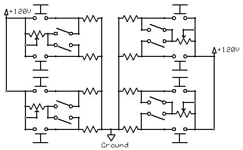
Also, Schematic 2 shows the wiring of the test fixture shown in Photo 3. This schematic also shows a small LED test board that can be made to test port pins configured as push-pull. The board was designed to provide a complete operable microprocessor system on a module that can be powered up and used without having to wire the basic operational components such as a regulator, crystal oscillator and programming interface connector.
The board`s DIP format, with two 0. 1 inch header rows, is well suited to connections on a solderless breadboard or socketed wiring on a perforated board as shown in In addition to providing a convenient hardware platform, several programming files are furnished on the documentation disk that allow fast checkout of the completed module. These files are Intel hex format files that can be downloaded to the module using its C2 programming header and the Silicon Laboratories Integrated Development Environment (IDE).
This provides an easy way to verify the functionality of port pins and commonly-used chip features such as the serial port and the external crystal oscillator. 25 MHz with Internal Clock - To verify the chip using the internal oscillator, load the 361-25I. hex. This allows you to verify the operation of the Target that uses a 24. 5 MHz internal oscillator and its serial port operating at a 9600 baud. 100 MHz with Crystal Clock - Load the 361_100X. hex file to verify the Target chip`s operation using a 24. 5 MHz external crystal oscillator, and a PLL-multiplied clock frequency of 100 MHz. With these settings, the serial port operates at a 38400 baud. 100 MHz with Internal Clock - To check the Target chip`s op 🔗 External reference
Related Circuits
There is, and always has been, a marked lack of good, inexpensive lighting controllers for small theatre groups or musicians. The LX-800 Lighting System was designed with these applications in mind. More: As I said, this is an ambitious...
The momentary switch utilized has a safety rating of 10A. If a switch is rated for a current that is too low, the instantaneous current during the first millisecond could cause the switch contacts to fuse together. To achieve...
Prototype board for 40-pin Atmel ATMega microcontrollers featuring a power supply circuit, an 8MHz crystal oscillator circuit, an RS232 port, a reset IC, a status LED, and a 10-pin STK ICSP port. Constructed from FR-4 material, 1.5 mm thick. The described...

The ISL62386 controller generates supply voltages for battery-powered systems. It features two pulse-width modulation (PWM) controllers that are adjustable from 0.6V to 5.5V, along with two linear regulators, LDO5 and LDO3, which provide fixed outputs of 5V and 3.3V,...
Datagoo is based on the ATMEGA328P microcontroller, widely used by hobbyists in various Arduino projects. It can be programmed via any computer with a USB port when paired with an FTDI FT232RL USB-Serial circuit. Cost-effectiveness and simplicity were prioritized...

This is a power generating method from sunlight. This method of power generation is simple and is taken from natural resource. This need only maximum sunlight to generate power. This project helps for power generation by setting the equipment...
Warning: include(partials/cookie-banner.php): Failed to open stream: Permission denied in /var/www/html/nextgr/view-circuit.php on line 713
Warning: include(): Failed opening 'partials/cookie-banner.php' for inclusion (include_path='.:/usr/share/php') in /var/www/html/nextgr/view-circuit.php on line 713