
ne602 vhf circuits
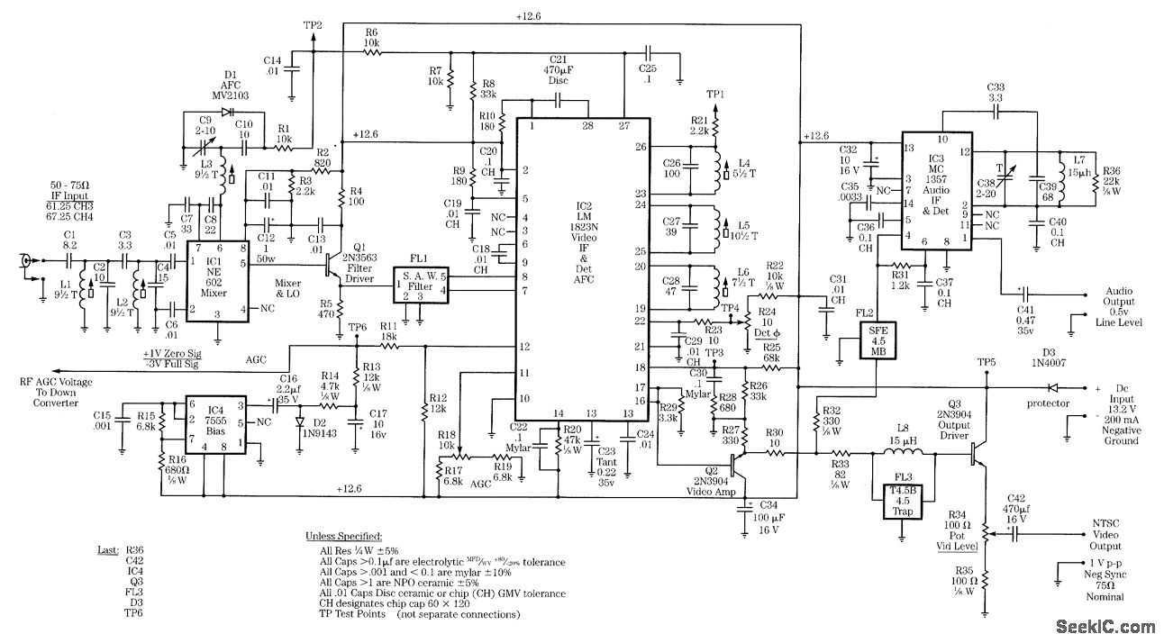
Radio-frequency (RF) schematics are essential for designing and implementing circuits that operate at high frequencies, typically ranging from 3 kHz to 300 GHz. The NE602 is a popular integrated circuit used in various RF applications, particularly in RF receivers. It functions as a double-balanced mixer, allowing for efficient frequency conversion, which is critical in RF communication systems.
RF receiver circuits are designed to capture and demodulate signals transmitted over the air. These circuits often include components such as antennas, amplifiers, mixers, filters, and demodulators. The design process begins with selecting an appropriate antenna that matches the frequency of interest, ensuring optimal signal capture.
Following the antenna, a low-noise amplifier (LNA) is typically employed to boost the weak incoming RF signals while minimizing added noise. The NE602 can then be utilized as a mixer to convert the RF signal to an intermediate frequency (IF) for easier processing. This is achieved by combining the RF signal with a local oscillator (LO) signal, which is also generated within the circuit. The choice of the IF frequency is crucial, as it affects the overall performance and selectivity of the receiver.
Subsequent stages in the RF receiver may include bandpass filters to eliminate unwanted signals and noise, ensuring that only the desired frequency range is processed. Finally, a demodulator is used to extract the information carried by the RF signal, which can be audio, video, or data.
In summary, RF receiver circuits encompass various components and design considerations that work together to effectively receive and process high-frequency signals. The NE602 plays a pivotal role in these designs, serving as a versatile mixer that facilitates efficient signal conversion and processing.Radio-frequency schematics (also see. ne602 datasheet and application note,.This page contain electronic circuits about Electronic RF receivers Circuits. This index has a wide collection of RF receivers, that can be.. 🔗 External reference
Related Circuits
This page is provided to the domain owner free by Sedo's Domain Parking. Disclaimer: The domain owner and Sedo maintain no relationship with third-party advertisers. References to any specific service or trademark are not controlled by Sedo or the...
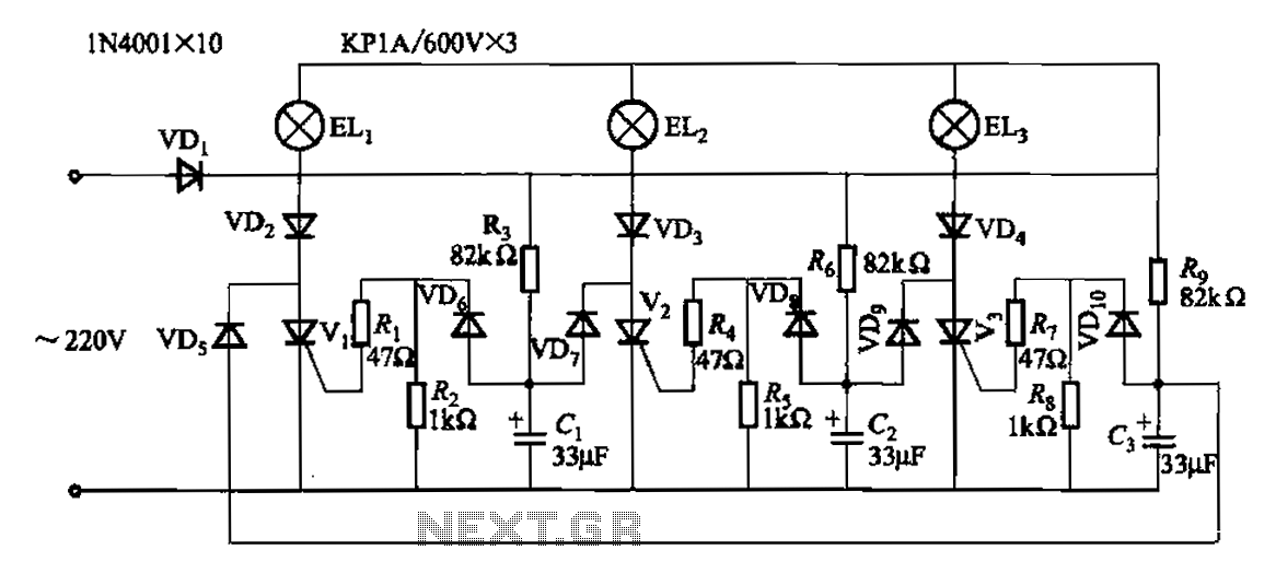
The circuit operates with a 220V mains supply through a diode (VDi) configured as a half-wave rectifier. Capacitors C1 to C3 are charged, and due to the lack of full synchronization in the charging process, a pilot thyristor is...
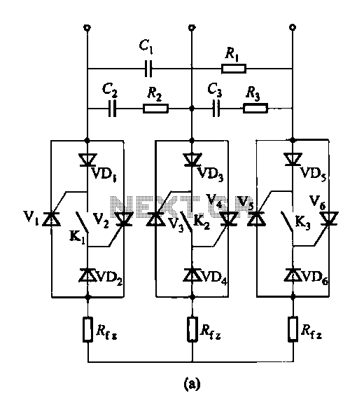
Figure 16-48 (a) illustrates the introduction of a six thyristor three-phase AC switching circuit, while Figure 16-48 (b) depicts the implementation of three triac circuits. These configurations are suitable for motors and other inductive loads. The six thyristor three-phase AC...
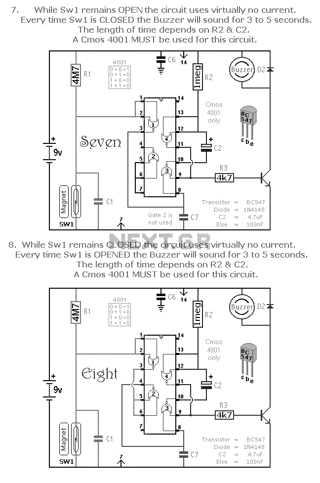
A selection of small self-contained CMOS alarm circuits is presented. The main features of each alarm are indicated on the circuit diagram itself. All circuits exhibit a very low standby current, making them suitable for battery operation. Each pair...
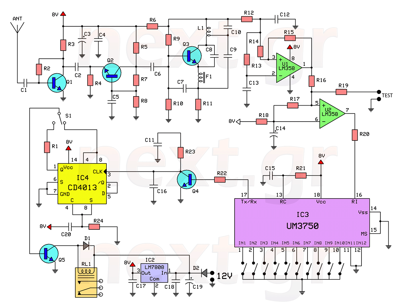
This circuit includes a 2048 radio remote control transmitter and a corresponding wireless receiver that features high reception sensitivity and low power consumption. The combination of these two components provides a highly reliable remote control system, suitable for various...
The MAX732/733 is a DC-DC current PWM step-up regulator. The MAX732 has an output voltage of +12V with a maximum output current of 200mA and an output voltage range of +4.0V to +9.3V. The MAX733 features an output voltage...