
Neon Desk lamp
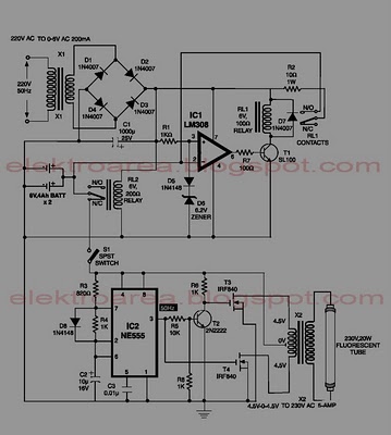
The circuit utilizes a 555 timer IC (IC1) configured in astable mode to generate a square wave output that drives a 6-inch, 4 Watt fluorescent tube. The circuit operates from a 12 V DC supply, drawing a current of approximately 300 mA. This design can also accommodate a universal AC/DC adapter, making it versatile for various power sources.
The 555 timer operates as an oscillator, generating a continuous square wave signal that is suitable for driving the fluorescent tube. The current output from the 555 timer is amplified by a transistor (TR1), allowing it to handle the higher current required by the fluorescent tube. The amplified voltage at the collector of TR1 is then fed into a transformer (T1), which steps up the voltage from a mains supply to a 6-0-6 V output. This step-up transformer is crucial for providing the necessary voltage to ignite and sustain the operation of the fluorescent tube.
To ensure reliable operation, it is recommended to use heat sinks for both TR1 and T1 to dissipate heat generated during operation. This will enhance the longevity and stability of the components. Additionally, a variable resistor (VR1) is included in the circuit to allow for adjustment of the output frequency or brightness of the fluorescent tube. It is advised to set VR1 to its maximum resistance of 5 K ohms before applying power to the circuit to prevent excessive current flow during initial power-up.
Overall, this circuit design emphasizes efficiency, utilizing readily available components to achieve good light output while maintaining low power consumption. The simplicity of the design, combined with the use of common stock parts, makes it an attractive solution for powering fluorescent lighting applications.The circuit is based on IC1, which is a 555 timer IC in astable mode. It will power a 6 inch 4 Watt fluorescent tube off a 12 volt supply, consuming 300 mA. It may also be powered by a suitably rated universal AC/DC adapter. Advantages of the design are: good light, low power consumption, and readily available stock parts. IC1`s current output is amplified by TR1, and the voltage at the collector is stepped up by T1, a mains to 6-0-6 V transformer. Heat-sinks are advised for TR1 and T1. Before applying power, VR1 should be advanced to a full 5 K. While power consumptio 🔗 External reference
Related Circuits
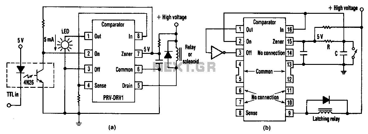
At half brightness, the lamp current is pulsed on and off by the voltage developed across the resistor and capacitor at the current-sense output. The current-sense output detects the lamp current. A basic pulse-width modulation (PWM) lamp-brightness control circuit...

This automatic light dimmer circuit enables controlled lighting that gradually turns on or off. The operation is as follows: when switch S1 is closed, capacitor C1 charges slowly. Once the voltage across C1 reaches 0.6 volts, transistor T1 begins...
This is a portable, high-power incandescent electric lamp flasher. It functions as a dual flasher (alternating blinker) capable of managing two independent 230V AC loads (bulbs L1 and L2). The circuit is entirely transistorized and operates on battery power....
This circuit is an IC-controlled emergency light system. It automatically switches on the light during a mains failure and includes a battery charger with overcharge protection. When the mains power is absent, relay RL2 is in a de-energized state,...
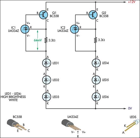
This LED lamp was originally designed for use on a budget solar-charged 12V electrical system. It is bright enough for comfortable reading at night and features constant LED brightness with diminishing battery voltage. The circuit uses six high-brightness white...
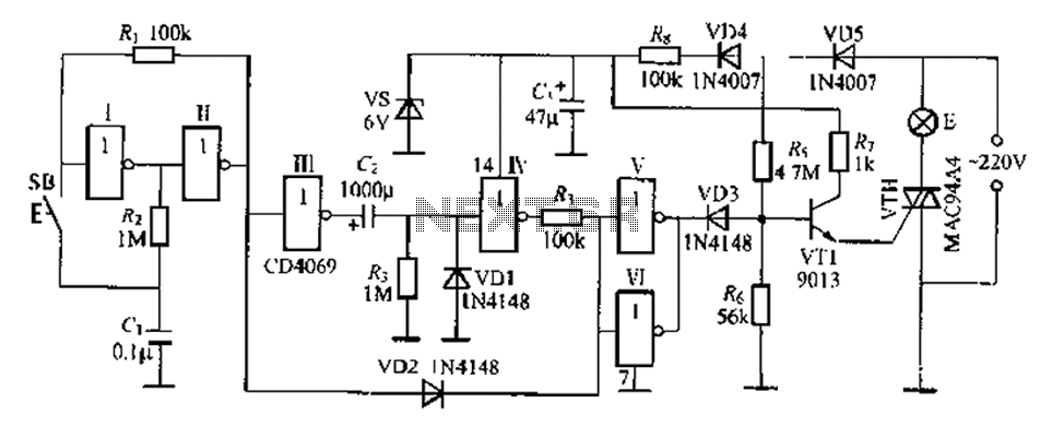
A delay lamp circuit is ideal for bedside tables, featuring a button (SB) that turns the light on and off. If the button is not pressed, the circuit maintains a delay before the light turns off. If the light...
Warning: include(partials/cookie-banner.php): Failed to open stream: Permission denied in /var/www/html/nextgr/view-circuit.php on line 713
Warning: include(): Failed opening 'partials/cookie-banner.php' for inclusion (include_path='.:/usr/share/php') in /var/www/html/nextgr/view-circuit.php on line 713