
Nicad Charger Uses Voltage Cut-Out
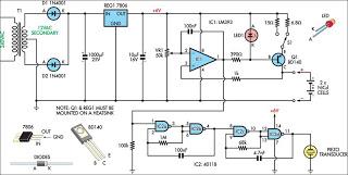
This circuit is designed to efficiently charge two nickel-cadmium (NiCad) cells, utilizing a constant current method to ensure optimal battery performance and longevity. It incorporates dual charging rates, allowing for flexibility based on the specific requirements of the cells being charged. The voltage cutoff feature is essential for preventing overcharging, which can damage the cells and reduce their lifespan. An audible alarm is included to alert the user when charging is complete or if any issues arise during the charging process.
The schematic typically includes a power supply section that provides the necessary voltage and current for charging. A current regulator circuit is integrated to maintain a constant charging current, which is critical for NiCad cells to avoid overheating and potential damage. The dual charging rates can be achieved through the use of selectable resistors or a microcontroller that adjusts the charging parameters based on user input or preset conditions.
The voltage cutoff mechanism is implemented using a comparator circuit that monitors the voltage across the cells. When the voltage reaches a predetermined threshold, the comparator will trigger a switching element, such as a relay or a transistor, to disconnect the charging current, thus preventing overcharging.
The audible alarm is typically driven by a simple oscillator circuit or a buzzer that activates when charging is complete or if a fault condition is detected, such as a short circuit or cell failure. This feature enhances user safety and provides an additional layer of monitoring for the charging process.
Overall, the circuit design emphasizes safety, efficiency, and user feedback, making it a reliable solution for charging NiCad batteries. Proper layout and component selection are crucial to ensure the circuit operates effectively within its specified parameters, contributing to the safe and efficient charging of the cells.This circuit charges two NiCad cells with a constant current and features dual charging rates, voltage cutoff and an audible alarm. The circuit is powered.. 🔗 External reference
Related Circuits
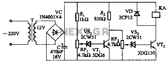
The circuit employs a transistor control mechanism. When the grid voltage is within the normal range, relay KA is activated, supplying power to the load. If the grid voltage falls below the minimum allowable threshold (adjustable via potentiometer RPz)...
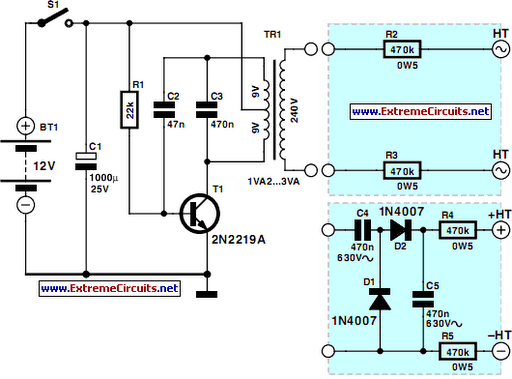
This project is designed to prevent unauthorized access to personal belongings left on a beach towel while swimming, and it can also be utilized in office or workshop settings. The circuit is compact and can be powered by simple...
Charger for all battery types power supply. This lithium battery charger circuit is dedicated to charging lithium batteries. It uses two chips: the voltage regulator LM317T and ICL7665, which warns microprocessors of overvoltage and undervoltage conditions. Charging is completed...
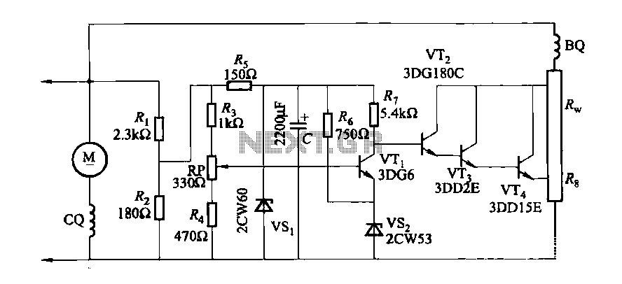
The DC generator automatic voltage regulator circuit is illustrated in Figure 7-53. This circuit is designed for a 40kW, 230V DC shunt complex machine, with a voltage change rate of up to 2.5 percent. In Figure 7-53, BQ represents...
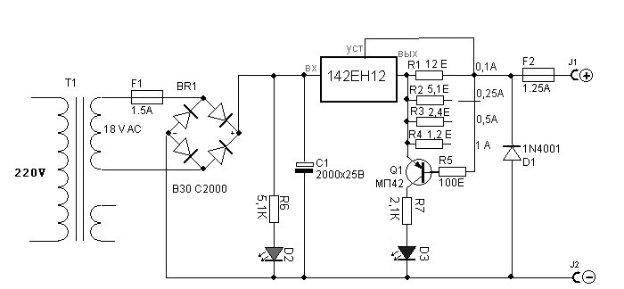
This circuit consists of two main components: a battery charger that provides a fixed output voltage of 5V DC, and a regulated power supply that allows for an adjustable output voltage ranging from 2 to 9 volts. The circuit design...
There are instances where a 5-V supply voltage is available, but certain components within the circuit require a lower voltage supply. In such cases, a voltage regulator from the Texas Instruments TPS62000 family is an excellent solution, particularly when...
Warning: include(partials/cookie-banner.php): Failed to open stream: Permission denied in /var/www/html/nextgr/view-circuit.php on line 713
Warning: include(): Failed opening 'partials/cookie-banner.php' for inclusion (include_path='.:/usr/share/php') in /var/www/html/nextgr/view-circuit.php on line 713