
NiCd Simple Smart Nicad Battery Charger circuit
The described NiCad battery charger circuit is designed to provide a reliable charging solution for NiCd batteries, which are commonly used in various applications due to their robustness. The circuit utilizes a constant current source configuration, which is essential for maintaining a steady charging current that prevents overcharging and damage to the batteries. Q2, as the main control element, regulates the charging current based on the feedback received from R1, ensuring that the current remains at approximately 50 mA, which is suitable for NiCd batteries.
The inclusion of LED D3 serves a dual purpose: it indicates the operational status of the charger and provides visual feedback that charging is in progress. The zener diode D2 plays a critical role in stabilizing the voltage at the base of Q2, ensuring that fluctuations in input voltage do not affect the charging current. This stability is crucial for the longevity of the batteries being charged.
The circuit’s ability to handle incorrect polarity is facilitated by the transistor Q1, which acts as a protective switch. If the battery is connected in reverse, the voltage at the base of Q1 will not be sufficient to turn it on, effectively preventing any current from flowing through Q2 and protecting the batteries from potential damage. However, it is important to note that while the circuit can charge multiple batteries in series, it lacks the capability to detect a single battery connected in reverse when other batteries are correctly oriented. This limitation necessitates careful attention during battery installation.
Powering the circuit requires a small transformer to step down the mains voltage, followed by a bridge rectifier to convert the alternating current to direct current, which is then filtered by an electrolytic capacitor to provide a smooth DC voltage for the charger operation. The design emphasizes the need for proper thermal management, hence the recommendation for a heat sink for Q2, as excessive heat can lead to component failure and reduced efficiency.
In summary, this NiCad battery charger circuit is an effective solution for charging NiCd batteries, combining essential features such as constant current regulation, polarity protection, and visual indicators, while also highlighting the importance of careful battery placement and thermal management.In appliance that appeal for aerial current, Nicad (NiCd) rechargeable array still has the angry achievement compared to NiMH and Lithium battery. The charger ambit actuality is acute in the way it handle the amiss polarity of the array placement. The core of this battery charger circuit is the Q2, configured a constant current source for the batt
ery. LED D3 and zener diode D2 make the voltage applied to Q2 base constant, therefore the voltage and the current across R1 is constant. Using the value shown in the schematic diagram, the current flow through R1 will be constant at around 50 mA.
You can see that the base of Q2 is supplied by R3, which is controlled by Q1. Look at the Q1 base, it`s controlled by the battery voltage, so Q1 won`t works if the battery is placed in wrong polarity. Just note that although this battery charger could charge four Nicad battery (in series), it can`t detect if one battery placed in wrong polarity while two or three other batteries are in right polarity.
A small transformer, a bridge diode, and an electrolytic capacitor is needed to supply this circuit. Remember to provide a sufficient heat sink for Q2. This circuit will work as long as the battery is not completely discharged, because its weak voltage is needed to trigger the Q1 transistor. 🔗 External reference
Related Circuits
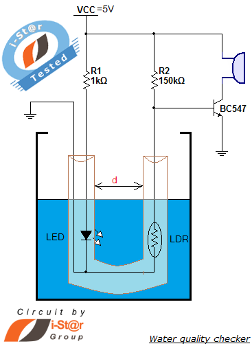
How to measure water purity and test water quality using a simple electronics project. Water purity measurement and water quality analysis can be performed using a water purity checker circuit. This circuit is constructed around a Light Dependent Resistor...
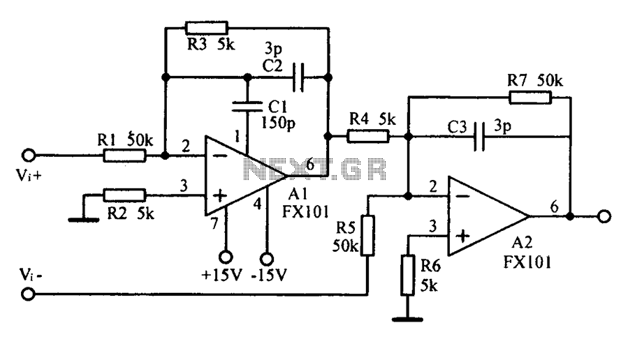
Common mode input voltage up to a difference of 100V enlarged circuit diagram. The circuit diagram described features a design capable of handling a common mode input voltage with a differential range of up to 100V. Such a configuration is...
It is advisable to prototype the entire circuit using a breadboard. This method simplifies the process significantly compared to attempting to determine the connections on a small printed circuit board. Prototyping a circuit on a breadboard allows for easy modifications...
This sawtooth generator circuit utilizes a 741 operational amplifier (op-amp) and functions as a musical sound synthesizer. The sawtooth input signal is continuously modified through potentiometer P2 to create varying waveforms. The sawtooth generator circuit primarily employs the 741 op-amp...
This page outlines how to create a simple theft deterrent that can be quite effective. The concept involves using a flashing red LED to indicate that the vehicle is protected. This device serves to safeguard the car from potential...
The circuit involves a switch (S1) that facilitates the release of current when it reaches the shut-off mechanism. The circuit operates by utilizing a switch (S1) that plays a crucial role in controlling the flow of current within the system....