
Nintendo 64 controller with PIC microcontroller
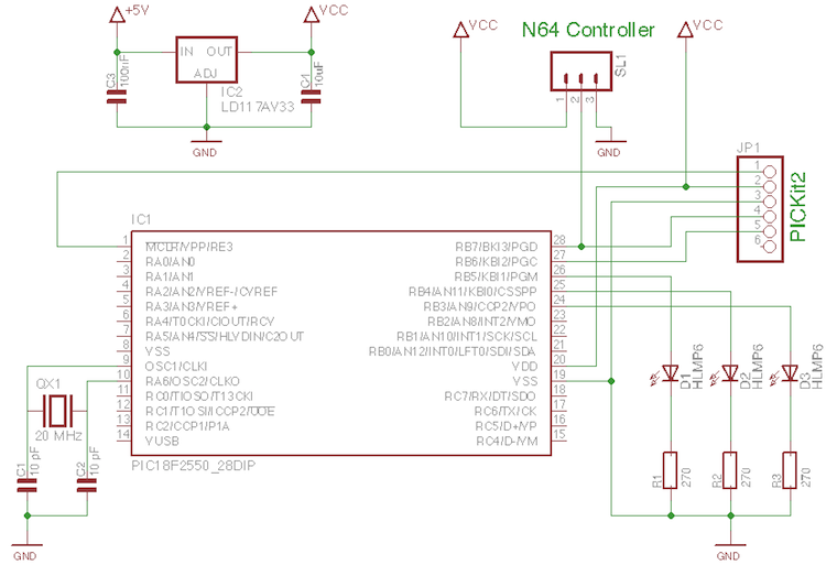
The circuit design incorporates a PIC18F2550 microcontroller, which is a versatile device featuring USB capabilities, making it suitable for interfacing with modern computing systems. The N64 controller's connection is designed to maintain a safe operating voltage, with the 3.3V regulator ensuring that the controller is not exposed to damaging levels of voltage. The use of three LEDs connected to specific GPIO pins provides immediate visual feedback on the status of the circuit, allowing for easy troubleshooting and validation of operation.
The serial communication protocol used by the N64 controller involves precise timing and signal generation, which is critical for accurate data transmission. The assembly language programming approach facilitates the fine control needed to generate the required signal shapes within the specified timing constraints. The instruction cycle timing and the relationship between oscillator frequency and instruction execution are essential for achieving the desired communication with the N64 controller.
In summary, this project exemplifies the integration of vintage gaming hardware with modern microcontroller technology, showcasing the potential for repurposing old devices into new applications. The methodology described provides a foundational understanding of interfacing with the N64 controller, which can be adapted for various projects involving microcontrollers and serial communication. Future developments may include expanding the project to include wireless communication capabilities, as hinted at with the inclusion of the RF transmitter.A few old N64 controllers lying around and figured that it would be pretty cool to use them to control other things. In this article I will describe in detail every step I took to achieve this. I`ve used a PIC microcontroller, but it should not be too hard to port the code to any other architecture.
The N64 controller has three connections. From right to left with the round side up: Ground, Data and VCC (3. 3V). Just plug some cables in the holes and you`re ready to go. The circuit I created for reading out the controller is shown in the schematic below. It is based around a PIC18F2550. I chose a pic from the 18F range, because I am interested in the USB capabilities, as I might try to use the N64 controller with a computer some day (future article maybe ). I did however limit my oscillator frequency to 20 MHz, so that everything should work on a 16F pic as well if you don`t need USB.
I`ve connected three LED`s to RB5, RB4 and RB3. They will provide some visual feedback so we can see if everything works properly. A 3. 3V voltage regulator provides the voltage for the board. The maximum voltage the N64 controller can handle is 3. 6V, so don`t exceed that. If you use 5V you will risk frying your controller. The N64 controller is connected to the board with a simple screw connector. Here the supply voltage is given, and the data pin is connected to the RB7 pin of the PIC18F2550. I`ve also connected a header (JP1) for the PICKit2. This allows me to program the PIC without having to take it out of the circuit ( ICSP ). At the moment it also provides the supply voltage to the board because I am to lazy to find a good power supply. Make sure you set the PICKit to 3. 3V instead of the default 5V for the reason I mentioned earlier. The image below shows the fully built circuit built on perfboard. The rectangular thing to the right of the microcontroller is a wireless RF transmitter. I will talk about this in a next article, but it is of no importance to us now. Now we`re going to take a quick look at the communication with the Nintendo 64 controller. The interface looks a little bit like one wire, but is still different. It`s a serial interface, which means that all the signals discussed here, will take place on one pin: the DATA (middle) pin of the connector (white wire in the pictures above).
The signal shapes used by the N64 controller for one and zero are shown below. As you can see these signals are very fast with a period of 4 uS and a resolution of 1 us! On a PIC microcontroller, one instruction cycle equals 4 oscillator cycles, which means that with a 20 MHz oscillator, 1 uS takes only 5 instruction cycles! To generate these signals, we will need a low-level programming language like assembly, as C just won`t cut it.
I will give as much information as needed, so if this is your first experience with assembly, you will be able to follow easily. A good reference for the PIC instruction set can be found here: PIC Instructions. Below both signal shapes I have included a very simple program to generate the signal in asm (of course there are other possibilities e.
g. with bsf and bcf). There are only three different instructions used: It`s easy to see that a combo of movlw with movwf can set a pin by modifying the PORTB register. As our N64 controller is connected to pin RB7, we set this pin high by sending the binary signal 0b10000000 to PORTB, which is 0x80 in hexadecimals.
Ofcouse sending 0x00 makes the pin 0. All three instructions we used take 1 instruction cycle (check the PIC 18F instruction set here ). This means that it is very easy to count every step. As I said previously: 1 uS takes 5 instruction cycles. That means that, to generate a zero, we have to set pin RB7 low, wait for 15 instructions, and then set it high for 5 instructions. I have counted and indicated the instructions that the pin is high with a bold font, and the instructions that it is lo
🔗 External reference
Related Circuits
The ICL7135 typical application schematic diagram is illustrated in the following circuit. This Analog to Digital (A/D) converter incorporates all necessary active devices on a single CMOS integrated circuit, featuring multiplexed BCD output and digit drivers. The ICL7135 is a...
The simplest form of motor controllers, apart from a basic on/off switch, is the contactor controller. This contactor controller is recommended for use in electric scooter projects. It is based on three 12V relays, two 12V batteries, two switches,...
Four way Traffic light controller which Has Red, Yellow and Green LEDS. It uses the AT89C2051. The four-way traffic light controller is an essential electronic system designed to manage traffic flow at intersections by controlling the operation of Red, Yellow,...
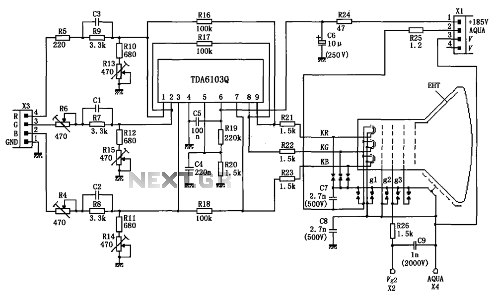
The circuit depicted in the figure integrates the TDA6103Q with a color picture tube, illustrating its practical application. The red, green, and blue (R, G, B) input signals are received from the input socket X3 and processed through a...
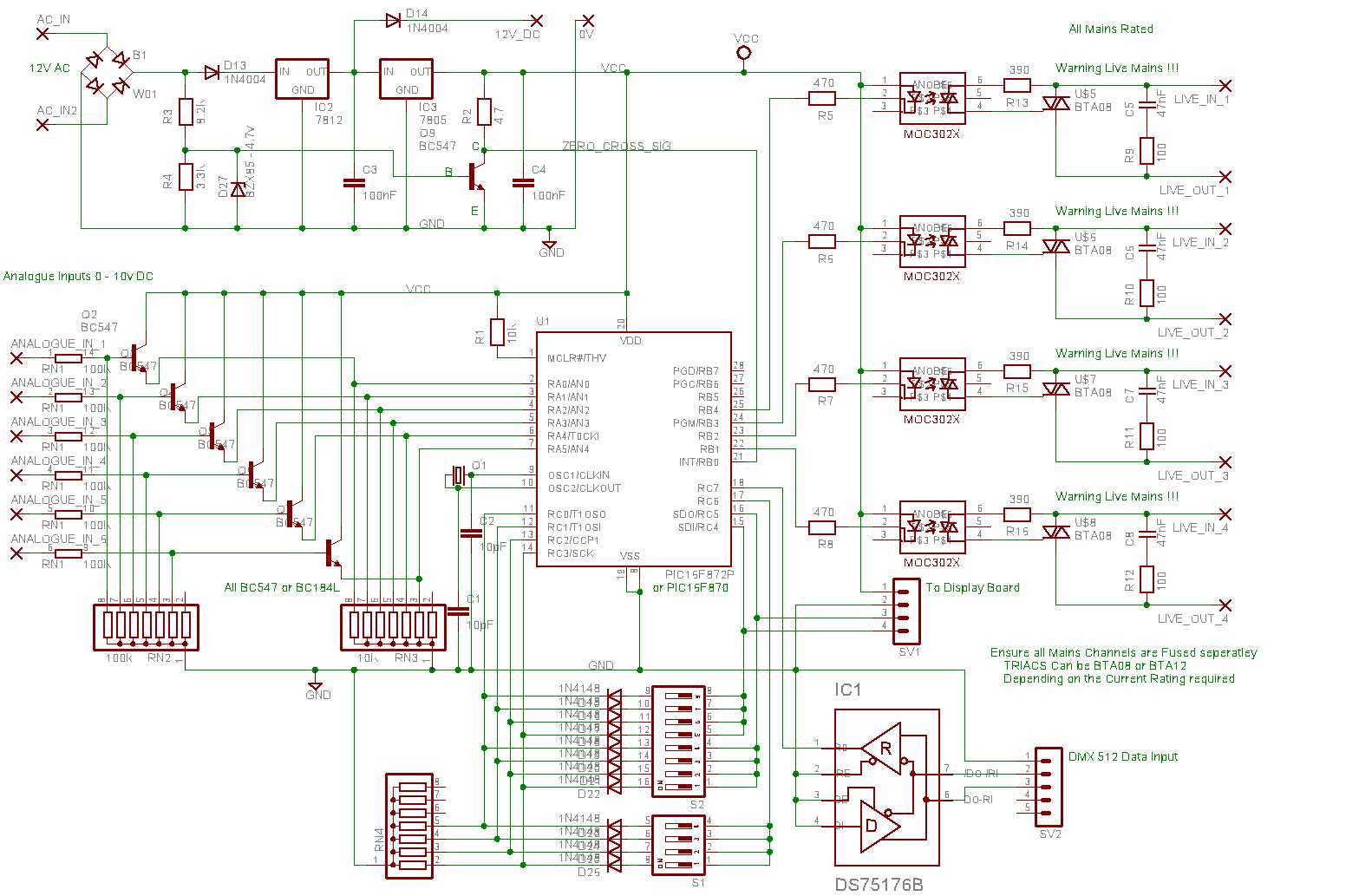
This unit receives DMX 512 data and Analogue (0-10V) data and uses these to phase angle control mains output. Features: DMX 512 data Input. Analogue (0-10V) DC Input. 4 Output channels. Remotely programmable Internally saved Presets. 3 Modes of...
Diode D1 and resistor R1 provide VDD isolation during the programming of 24-pin devices. The jumper J3 must be shorted for 24-pin device programming and left open for 28-pin device programming. The following EEPROMs are pin-compatible with their EPROM...
Warning: include(partials/cookie-banner.php): Failed to open stream: Permission denied in /var/www/html/nextgr/view-circuit.php on line 713
Warning: include(): Failed opening 'partials/cookie-banner.php' for inclusion (include_path='.:/usr/share/php') in /var/www/html/nextgr/view-circuit.php on line 713