
Nissan Sentra 1.6 Liter Manual Transmission Starter Circuit Wiring Diagram

The Nissan Sentra 1.6 Liter manual transmission starter circuit wiring diagram provides a visual representation of the electrical connections involved in the starting system of the vehicle. This diagram is essential for understanding how the starter motor, ignition switch, battery, and other components are interconnected to facilitate engine starting.
The circuit typically includes the following key components: the battery, which supplies the necessary voltage; the ignition switch, which activates the starter relay; the starter relay, which controls the flow of current to the starter motor; and the starter motor itself, which engages the engine flywheel to initiate the engine's operation.
In a typical setup, the ignition switch is connected to the battery and the starter relay. When the ignition switch is turned to the start position, it sends a signal to the starter relay, which then closes its contacts and allows current to flow from the battery to the starter motor. This action engages the starter motor, which cranks the engine.
Additionally, safety features may be included in the circuit to prevent accidental starting, such as neutral safety switches that ensure the vehicle is in the correct gear before allowing the starter to engage. The wiring diagram will indicate the specific colors and gauge of wires used, as well as the locations of connectors and any fuses or circuit breakers that protect the system from overloads.
Understanding this wiring diagram is crucial for troubleshooting starting issues, performing repairs, or making modifications to the starter circuit in the Nissan Sentra 1.6 Liter with a manual transmission. Proper interpretation of the schematic ensures that technicians can accurately diagnose problems and implement effective solutions.Nissan Sentra 1.6 Liter Manual Transmission Starter Circuit Wiring Diagram. 🔗 External reference
Related Circuits
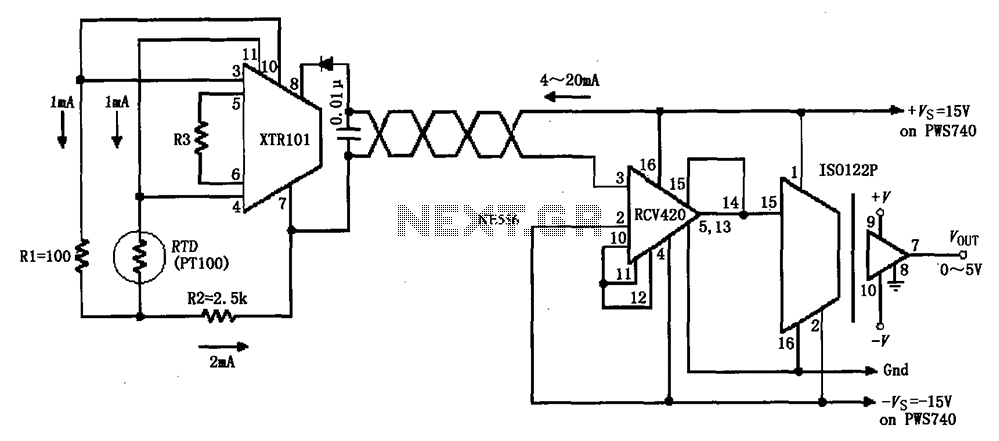
The circuit comprises an isolated RTD loop current configuration utilizing the XTR101 for transmitting loop current and the RCV420 for receiving it. The instrumentation amplifier detects changes in temperature via a resistance temperature detector (RTD), converting these changes into...
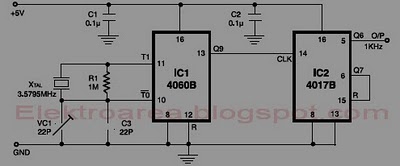
This circuit is designed for accurate time-base generation utilizing the commonly available 3.5795 MHz crystal, which is frequently used in telecommunication equipment. A crystal-based oscillator combined with a divider IC chain or a similar circuit, such as an ASIC,...
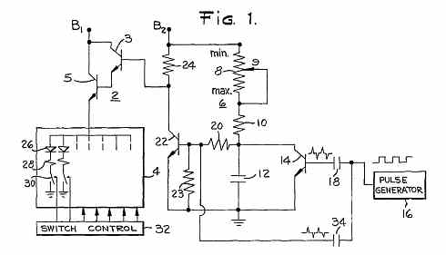
LED brightness control circuit: A simple circuit can be used to control the brightness level of an LED display. The LED brightness control circuit is designed to adjust the illumination level of an LED display according to user preferences or...
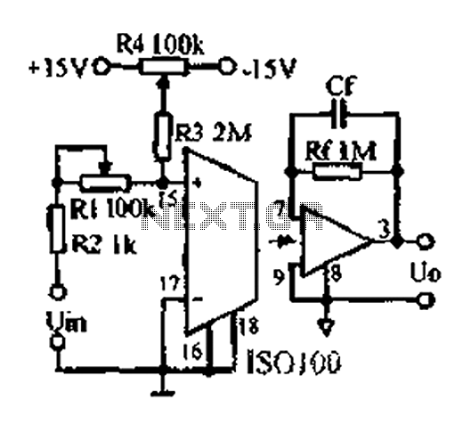
An adjustable gain test is conducted in preparation for an isolation amplifier circuit, utilizing the optical coupling isolation amplifier ISO100. This adjustable gain can form part of a test device for the isolation amplifier. The circuit gain can be...
Most homes today have at least a few infrared remote controls, whether for the television, video recorder, stereo, or other devices. Despite this, many individuals have experienced frustration when a light remains on after settling into a comfortable chair...
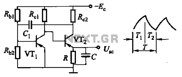
Common non-sinusoidal oscillator circuit, waveform and frequency formula - sawtooth oscillator - use multivibrator. The sawtooth oscillator is a type of non-sinusoidal waveform generator that produces a triangular or sawtooth-shaped output signal. This oscillator is commonly utilized in various applications,...