
Noisy-signals-filter
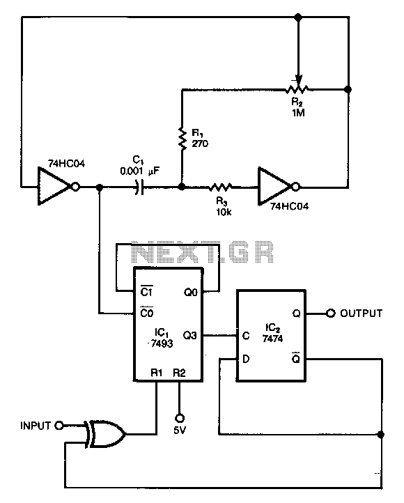
This circuit filters noise, such as glitches and contact bounce, from digital signals. It can be easily adjusted for a wide range of noise frequencies. The circuit's output changes state only if the input differs from the output long enough for the counter to count eight cycles. If the input changes before the counter reaches its maximum count, the counter resets without clocking the output of flip-flop IC2. The resistor R2 is used to set the frequency of the two-inverter CMOS oscillator, which clocks the counter. The oscillator should be adjusted so that its period is one-eighth that of the noise intended for elimination.
This circuit serves as an effective noise filter for digital signals, particularly in applications where contact bounce and transient glitches can lead to erroneous signal interpretation. The primary function is to ensure that the output state of the circuit remains stable unless the input signal remains consistent over a specified duration, allowing for reliable signal processing.
The core of the circuit includes a counter that monitors the input signal. This counter must count to eight cycles before any change in the output state occurs. This design choice introduces a debounce mechanism, effectively filtering out brief fluctuations in the input signal that do not represent legitimate state changes. If the input signal returns to its original state before the counter completes its count, the counter resets, preventing any unintended state changes in the output.
The oscillator, built using two CMOS inverters, generates a clock signal that drives the counter. The frequency of this oscillator is crucial, as it determines the responsiveness of the system. By adjusting the resistor R2, the frequency can be tuned to achieve an oscillator period that is one-eighth of the targeted noise frequency. This ensures that the circuit is optimally configured to filter out specific noise characteristics while maintaining the integrity of the desired digital signals.
Overall, this circuit is a valuable tool for enhancing the reliability of digital systems by mitigating the effects of noise and ensuring that only valid signals are processed.This circuit filters noise, such as glitches and contact bounce, from digital signals. You can easily adjust the circuit for a wide range of noise frequencies. The circuit"s output changes state only if the input differs from the output long enough for the counter to count eight cycles. If the input changes before the counter reaches its maximum count, the counter resets without clocking the output of flipflop, IC2.
You use R2 to set the frequency of the two-inverter CMOS oscillator, which clocks the counter. Simply adjust the oscillator such that its period is one-eighth that of the noise you want to eliminate. 🔗 External reference