
Non-diode rectifier
In the context of electronic circuit design, the use of a single-supply operational amplifier (op-amp) in a bipolar signal environment presents unique challenges. The op-amp is typically designed to operate with dual power supplies, which allows for a more straightforward handling of both positive and negative signal swings. However, when constrained to a single supply, the design must adapt to accommodate the bipolar nature of the input signals.
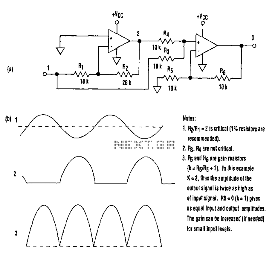
The proposed circuit (A) demonstrates a solution to this problem by utilizing a high-precision full-wave rectifier configuration. This approach eliminates the need for diodes, which are commonly used in traditional rectifier designs. Diodes introduce forward voltage drops and can limit the frequency response of the circuit. By employing an op-amp in the rectification process, the circuit achieves improved accuracy and a wider bandwidth.
The full-wave rectifier circuit operates by taking advantage of the op-amp's ability to amplify and invert signals. The feedback network around the op-amp is configured to ensure that both halves of the input waveform are utilized effectively. This results in a rectified output that closely follows the input signal's envelope, providing a high-fidelity representation of the original waveform.
Moreover, the high-frequency limit of the op-amp plays a crucial role in determining the performance of the rectifier. The selected op-amp must have a sufficient gain-bandwidth product to handle the frequencies of interest without significant distortion. The design may also include additional passive components, such as resistors and capacitors, to fine-tune the response and stability of the circuit.
In summary, the circuit in (A) exemplifies a sophisticated approach to rectification using a single-supply op-amp in a bipolar signal environment. By eliminating diodes and leveraging the op-amp's capabilities, the design achieves high precision and an extended frequency response, making it suitable for various applications where accurate signal processing is required. As we all know, when a single-supply op amp, a bipolar signal environment to achieve a simple function may be difficult. Sometimes the need for additional operational amplifier s and other electronic components. Think about it, this pattern is there any advantage The answer lies in the simple circuit in (A). Do not need diodes, this circuit is a high-precision full-wave rectifier, the rectifier is equal to the op amp itself with high-frequency limit.
Related Circuits
A rectifier is an electronic circuit that converts AC voltage to DC voltage. It can be implemented using a combination of capacitors and diodes. The unique property of diodes, which allows current to flow in a single direction, is...
The schematic illustrates how +25V DC and -25V DC are generated to supply power to two stereo amplifiers. An 80VA power transformer with a 240V/36V center-tapped secondary winding is utilized. The secondary output of the transformer is rectified using...
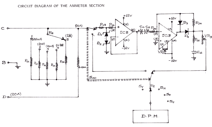
Studying current measurement is essential for various measuring techniques. The current parameter primarily indicates power consumption in a circuit, based on the resistance value. Measuring current is often more convenient than measuring voltage to assess power output and determine...
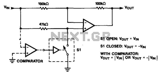
The operational amplifier (op amp) can function as either an inverter or a buffer, depending on the polarity controlled by a switch. When configured as a buffer, the gain remains constant at 1. In contrast, when functioning as an...
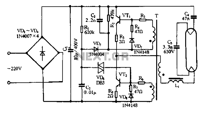
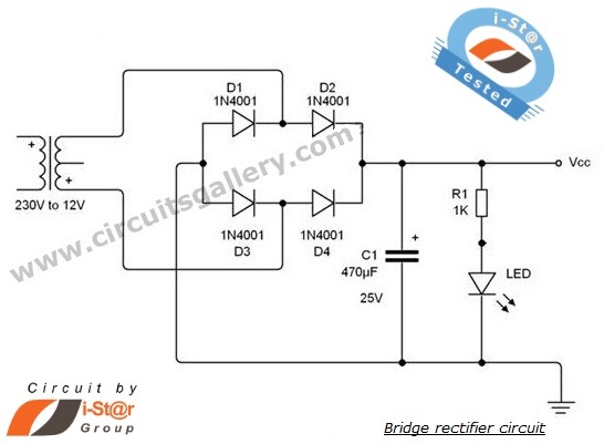
Bridge rectifier circuit in the electronic ballast application circuit The bridge rectifier circuit is a crucial component in electronic ballast applications, primarily utilized for converting alternating current (AC) to direct current (DC). This conversion is essential for powering various electronic...
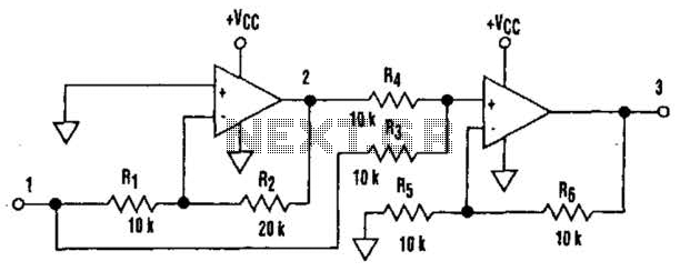
It is well understood that utilizing single-supply operational amplifiers (op amps) can present challenges when implementing simple functions in a bipolar signal environment. Often, this necessitates the use of additional op amps and other electronic components. Considering this, it...
Warning: include(partials/cookie-banner.php): Failed to open stream: Permission denied in /var/www/html/nextgr/view-circuit.php on line 713
Warning: include(): Failed opening 'partials/cookie-banner.php' for inclusion (include_path='.:/usr/share/php') in /var/www/html/nextgr/view-circuit.php on line 713