
Norton-amplifier
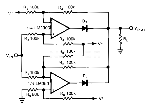
The non-inverting amplifier has a gain of R2/R3 (1 in this case) and produces a voltage of V during a positive excursion of Vin with respect to ground. The inverting amplifier accommodates the negative excursions of V; its gain is given by -R6/R7, which equals -1 to maintain symmetry with the non-inverting amplifier. R9 provides adjustment for the symmetry, supply variations, and offsets. Even though the circuit operates on a single supply, Vin can go negative to the same extent that it goes positive.
The described circuit consists of a non-inverting amplifier and an inverting amplifier arranged to achieve a symmetrical response to input voltage variations. The non-inverting amplifier utilizes resistors R2 and R3 to establish a gain of 1, which means the output voltage (V) mirrors the positive input voltage (Vin) when it exceeds ground potential. This configuration ensures that any positive fluctuations in Vin result in corresponding increases in the output voltage, thereby facilitating straightforward amplification of positive signals.
Conversely, the inverting amplifier is designed to handle negative excursions of the input voltage. The gain of this amplifier is determined by the ratio of resistors R6 and R7, yielding a gain of -1. This negative gain ensures that for every increase in the negative input voltage, the output voltage decreases symmetrically, maintaining a balanced response with the non-inverting section of the circuit. The symmetry is crucial for applications requiring consistent performance across both positive and negative inputs.
Resistor R9 plays a vital role in fine-tuning the circuit's performance. It allows for adjustments to account for variations in symmetry, supply voltage fluctuations, and any inherent offsets that may arise during operation. This adaptability is particularly beneficial in applications where precise signal processing is required.
An important characteristic of this circuit is its ability to operate on a single supply voltage while still accommodating input voltages that can swing both positively and negatively. This feature enhances the circuit's versatility, making it suitable for a variety of applications where the input signal may not be confined to a strictly positive range. Overall, the combination of the non-inverting and inverting amplifiers with appropriate resistive components provides a robust solution for amplifying signals with both positive and negative excursions.The noninverting amplifier has a gain of R2/R3 (1 in this case) and produces a voltage of V,"" during a positive excursion of Vin with respect to ground. The inverting amplifier accommodates the negative excursions of V..; its gain is given by -R6/R7, which equals -1 to maintain symmetry with the noninverti;1g amplifier.
R9 provides adjustment for the symmetry, supply variations, and offsets. Even though the circuit operates on a single supply, Vin can go negative to the same extent that it goes positive. 🔗 External reference