
Null detector
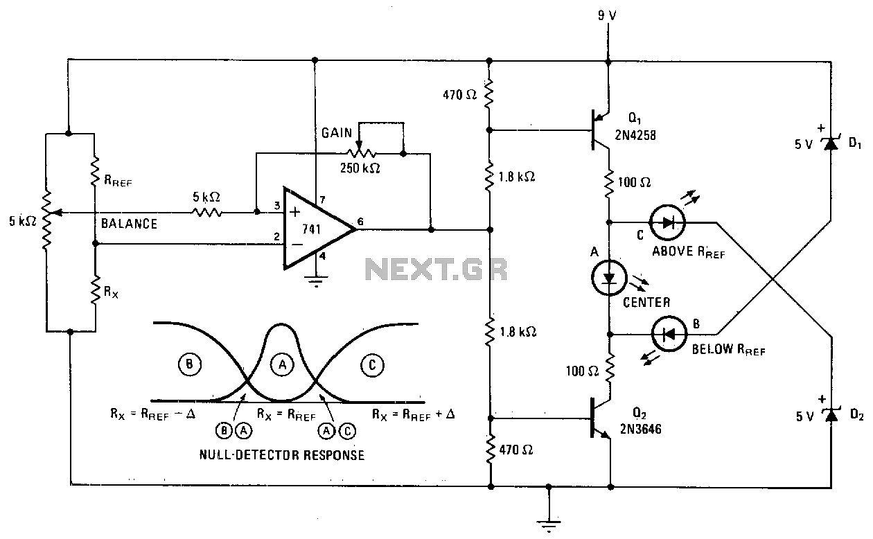
The null detector circuit is designed to provide a visual indication of the relationship between a test resistor (R*) and a reference resistor (Rref) using an LED as an output indicator. The core component of this circuit is the operational amplifier (op-amp), specifically the 741 model, which is configured in a differential mode to compare the voltages across the two resistors.
When the resistance of R* matches Rref, the op-amp output stabilizes at approximately half of the supply voltage, which is typically around 4 volts in a dual-supply configuration. This mid-range voltage causes LED A to turn on, providing a clear visual signal that the two resistances are equal.
In scenarios where R* is either less than or greater than Rref, the op-amp output will either increase or decrease, leading to the activation of one of two transistors in the circuit. The transistor that is turned off will stop conducting, while the other transistor will allow current to flow through either output B or C, depending on the direction of the voltage difference. This configuration ensures that the circuit can indicate both conditions of being below or above the reference resistance.
The null detector circuit can be further enhanced by incorporating additional features such as hysteresis to prevent false triggering or adding a more sensitive LED output to indicate small deviations from the null point. Additionally, the circuit could be designed to include adjustable reference resistance, allowing for greater versatility in testing various resistor values. Overall, this simple yet effective design serves as a practical tool in electronic testing and measurement applications.Null detector uses simple LED readout to indicate if test resistor R* is below, equal to, or greater than test resistance Rref. IfR* = Rref, the 741 output sits at midpoint value of 4 volts and LED A lights Otherwise, the output of the 741 turns off one transistor and diverts current from the other transistor through B or C, depending on the polarity of the input voltage difference. Null-detector response is illustrated. 🔗 External reference
Related Circuits
This project has not been called a GOLD detector as this name has been left for the more complex detectors that actually discriminate between gold and other metals. There is an enormous difference between detecting gold and ordinary metals...
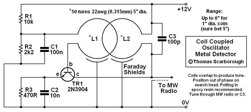
A Coil Coupled Operation Metal Detector made from readily obtainable components and using an ordinary medium receiver as a detector. The metal detector shown here may well represent a new genre. At any rate, after some exposure, it is...

Useful for liquids level detection and proximity devices. Up to 50 cm range, optional relay operation. This circuit is useful in liquids level or proximity detection. It operates detecting the distance from the target by reflection of an infra-red...
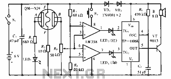
The QM-NJ9 is an alcohol sensor that detects the presence of alcohol by measuring the resistance values between points A and B. When alcohol is detected, the resistance decreases, leading to an increase in potential at point B. As...
An arrangement was established that functions effectively. In the siren circuit, the reed switch was shorted as illustrated. The power supply was removed, and a new configuration was created. The described siren circuit utilizes a reed switch, which is a...
This circuit utilizes a complementary pair consisting of an NPN metallic transistor T1 (BC109) and a PNP germanium transistor T2 (AC188) to detect heat in the environment, such as that produced by a fire, and activate a siren. The...