
obstruction detector with 12c508 ir
The project incorporates an IR proximity detection system designed to operate in various environmental conditions. The use of a five-wire or four-wire connection enhances versatility in setup. The adjustable resistor or trimpot allows for fine-tuning of the detection range, accommodating a wide array of user requirements. The IR proximity detector utilizes a robust detection algorithm that improves reliability by differentiating between valid and false detections based on the frequency of hits during the active and inactive cycles of the IR LED.
The implementation of a dual counter system allows for dynamic monitoring of detection validity, with specific thresholds ensuring that only significant detections are acknowledged. This design choice mitigates the influence of ambient noise, which is particularly crucial in environments with fluctuating light conditions. The ability to modify the sensitivity and response thresholds provides users with the flexibility to adapt the system to specific applications, ranging from simple proximity sensing to more complex robotic navigation tasks.
The availability of both 38 kHz and 56.7 kHz models caters to different application needs, allowing users to select a frequency that best suits their operational environment. The comprehensive kit, including all necessary components and clear documentation, facilitates ease of assembly and deployment. This project not only serves as an educational tool for those new to PIC programming and electronics but also as a practical solution for implementing proximity sensing in various robotics and automation projects.This project is inspired by the DPRG IRPROX project. They have a pretty good PCB layout and idea. I would like to thank them for posting their project for all of us to see and learn from, I wouldn`t have started PIC programming without them, or at least not nearly as quickly come up to speed! The pinout on my board allows either a five-wire or a f our-wire connection to be made the former uses a disable line if desired. You can also put in a resistor or use a trimpot to adjust range. The trimpot locations are very generic, most pots will fit. Be careful not to adjust pot to 0 ohms! The IR proximity detector works very well, even in a brightly lit noisy environment. Instead of modulating the IR LED for 600us and then looking for a detection, I now look for a detection after every on/off cycle of an IR LED and count the number of hits that I get. I also look during the off` cycle when none of the IR LEDs are on and count the number of false hits that I get there.
If I get more good hits than false hits then I say its a true detection. I then increment a counter as a sort of timer, when it passes a certain threshold, I notify a hit. At this time I check to make sure that a minimum number of good hits has been attained. At the same time I keep track via another time-out counter of noise hits. When this counter passes a certain threshold it then removes any detection that has been set. I fiddled a lot with the various threshold values for minimum number of good hits, time-out values and divisors for updating the false hit counts, and finally settled on the ones that currently used. I`m calling it a success and moving on to other projects! The source code for the, uhm, DLC IR proximity detector can be downloaded below as well as the PDF documentation for this kit.
I am now selling the complete kit, it was brought up to me that the exorbitant shipping costs from some distributors makes a full kit a real value added. So, here it is. The board, PIC, LEDs IR components and resistors as well as instructions are for sale. . I will make this in either 38KHz or 56. 7KHz models. [url=mailto:dlc@verinet. com]Contact me[/url] if you areinterested. Bulk buys of 10 or more or robotics clubs get discounts! 🔗 External reference
Related Circuits
This circuit employs a synchronous demodulator to separate a 1 KHz signal from noise and measures the amplitude of the 1 kHz signals once a second at about 60 microvolts per count then sends the measurements via an RS-232...

When the receiver is tuned to a medium wave radio station, feedback howl caused by the transmitter may occur when the coil and radio are positioned above or near a metal object. The search head is constructed from a...

This simple circuit can be utilized to activate various devices, such as microcontrollers, relays, secret alarms, or robot applications. It can also be used to turn on LED1, which remains illuminated as long as the metal plate is touched....
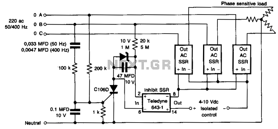
This circuit prevents damage to the load due to incorrect phasing. The three power solid-state relays (SSRs) are only permitted to turn on for a phase sequence where phase A leads phase B. If phase A lags phase B,...
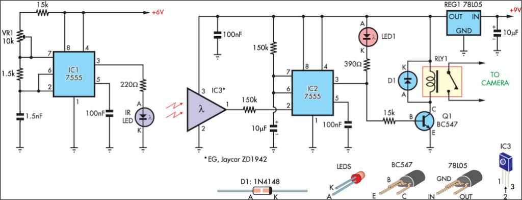
This circuit serves as an alternative to the infrared beam break detector discussed in the June 2009 issue of Silicon Chip. It aims to provide a more efficient solution for detecting interruptions in an infrared beam. This alternative infrared beam...

This circuit detects the 20 Hz, 86-V rms ring signal on telephone lines and initiates action in an electrically isolated circuit. Typical applications include automatic answering equipment, interconnect/interface systems, and key systems. The illustrated circuits are basic designs intended...