
Offline-converter
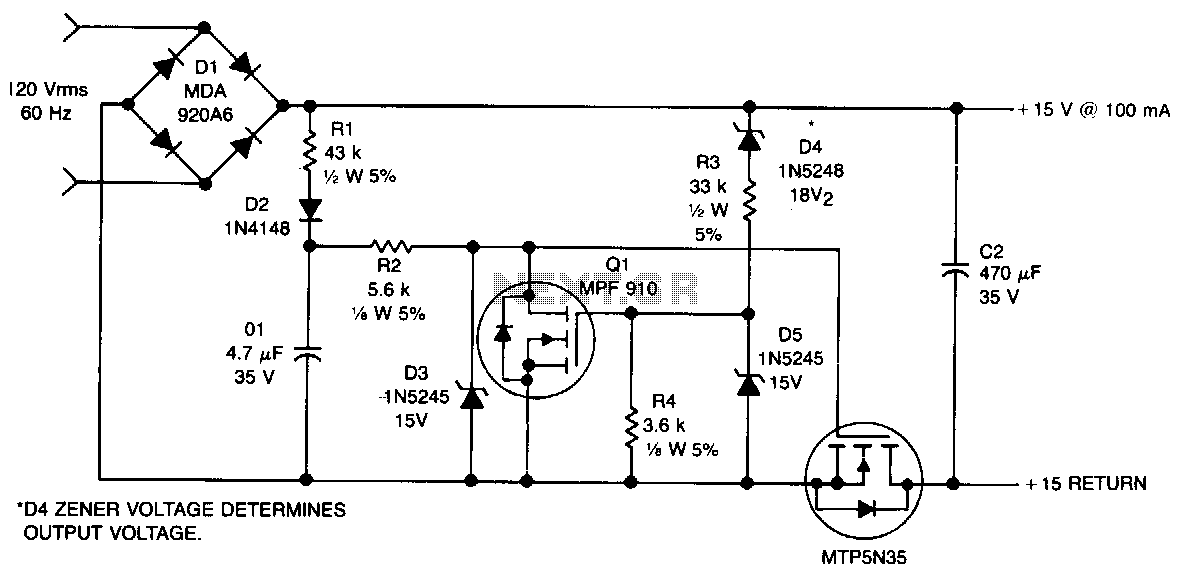
This non-isolated, unregulated converter with minimal components serves as a bridge between low-power zener regulation and the higher power applications of a 60-Hz input transformer. It is designed for scenarios where a non-isolated power supply can be utilized safely. The circuit functions by conducting only during the low-voltage segment of the rectified sine wave. R1 and D2 charge C1 to approximately 20 V, which is sustained by Q1. This voltage is then applied to the gate of Q2, activating it. When the rectified output voltage surpasses the zener voltage of D4, Q1 activates, shunting the gate of Q2 to ground, thereby deactivating it.
The described circuit operates as a non-isolated, unregulated converter, which is particularly useful in applications where simplicity and low component count are essential. The converter’s architecture allows it to efficiently utilize the low-voltage portions of the rectified AC waveform, ensuring that the output voltage remains within acceptable limits for low-power applications.
In this configuration, R1 and D2 play pivotal roles in establishing the initial charging of capacitor C1. Once charged, C1 holds a voltage of approximately 20 V, which is crucial for controlling the operation of transistor Q1. Q1 acts as a regulator by maintaining the voltage across C1 and ensuring that the gate of Q2 receives the appropriate voltage to turn on when necessary.
Transistor Q2 is responsible for delivering power to the load. When the rectified output voltage rises above the zener voltage set by D4, the voltage at the gate of Q2 is shunted to ground via Q1. This action turns off Q2, effectively preventing excessive voltage from reaching the load. The circuit thus provides a protective mechanism against overvoltage conditions, ensuring the safety and reliability of the power supply.
The design is well-suited for applications requiring low power and where isolation is not a critical factor. It is important to consider thermal management and component ratings to ensure reliable operation, especially in environments where the converter may be subjected to varying load conditions. Overall, this non-isolated converter offers a practical solution for low-power applications while maintaining simplicity and efficiency in its design.This nonisolated, unregulated, minimum component converter fills the void between low-power zener regulation and the higher power use of a 60-Hz input transformer. It is intended for use where)"er a nonisolated supply can be used safely. The circuit operates~by conducting only during the low-voltage portion of the rectified sine wave. Rl and D2 charge Cl to approximately 20 V, which is maintained by Ql. This voltage is applied to the gate of Q2, turning it on. When the rectified output voltage exceeds the zener voltage ofD4, Ql turns on, shunting the gate of Q2 to ground, turning it off. 🔗 External reference