
Only one-way operation of the automatic control circuit of the motor
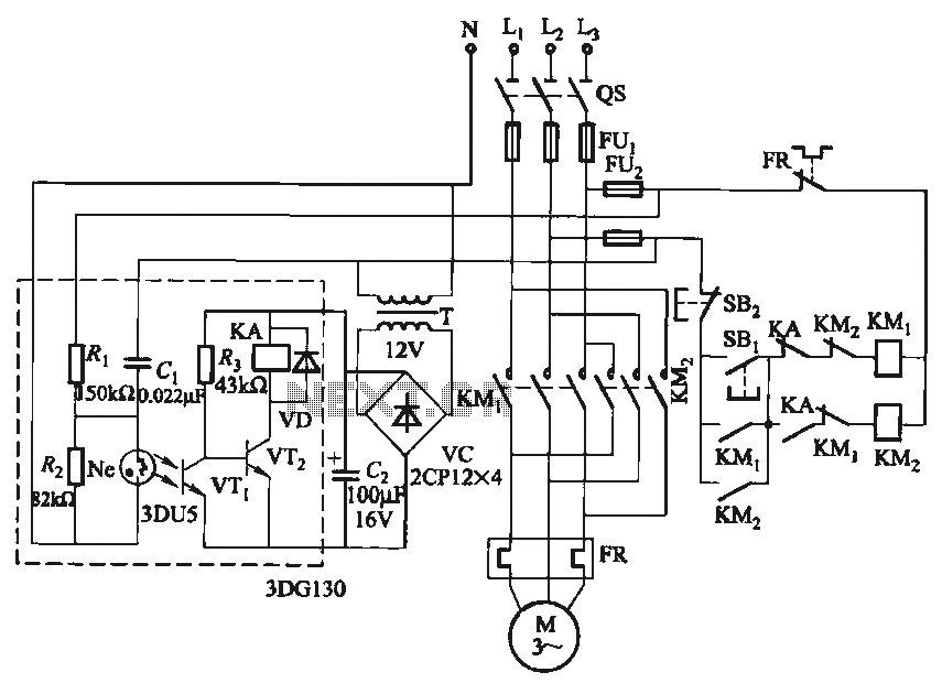
The described circuit employs a phase sequence detector to ensure that the motor operates correctly under varying conditions. The neon bulb serves as an indicator of the phase sequence status; when it is illuminated, it signifies that the phase sequence is incorrect. The relay (KA) acts as a safety mechanism, preventing the motor from starting if the phase sequence is not as required. The use of two relays, KA and KMz, allows for a fail-safe operation: KA ensures that the motor does not start under incorrect conditions, while KMz provides a means to maintain motor operation even when the phase sequence is altered.
This circuit can be particularly beneficial in industrial settings where motors are frequently subjected to changes in power supply conditions. By implementing this phase sequence control mechanism, the risk of equipment damage is significantly reduced, and operational reliability is enhanced. The design should ensure that all components, such as relays and indicators, are rated for the specific voltage and current levels associated with the motor and power supply to maintain safety and efficiency. Proper installation and regular maintenance of this circuit will contribute to its longevity and the overall safety of the motor operation.In some places, allowing only a specific direction by the motor running, even when the power supply phase sequence for some reason (such as outside line after overhaul wrong) while inverted, but also to ensure that the motor running in the specified direction. Otherwise, it will cause physical and equipment do so. The phase sequence can be used for this determination is to be controlled. Circuit shown in Figure 3-90. When the power supply phase sequence is correct, that is, U, V, W phase sequence when, Ne neon bulb does not light, relay device KA pull, press the start button SBi, contact KMi pull the motor starts running forward.
If the power supply phase sequence right, Ne shiny, KA released. Press SBi, KMz suction units, the motor will change the phase sequence followed by people power, the motor still running forward start.
Related Circuits
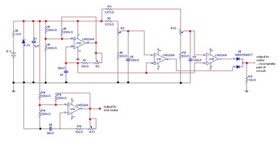
The goal is to control the speed of a 6-volt brush DC motor using a linear potentiometer and to create an oscillating speed effect, with the oscillation frequency also adjustable via a linear potentiometer. The desired complete cycle peak-to-peak...
This project outlines the construction of a Brushed Motor Electronic Speed Controller (ESC) for cars and boats using a Microchip 12F675 PIC and a limited number of standard components. This ESC is a revised version of an earlier aircraft...
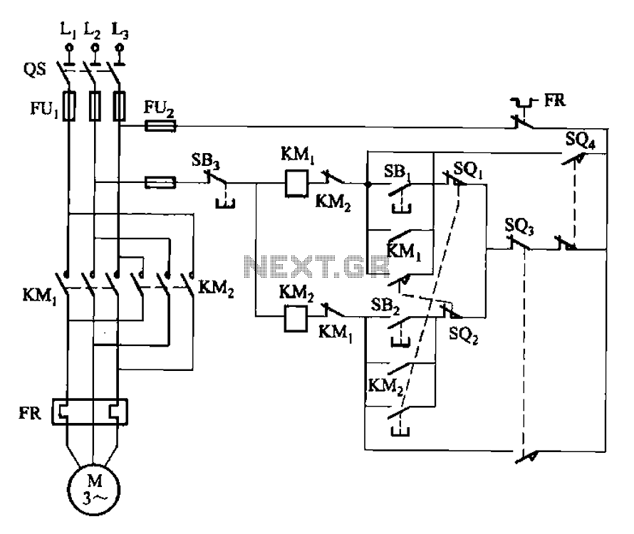
The circuit illustrated in Figure 3-132 represents an automatic round-trip plug braking circuit. To prevent or limit malfunctions of switch SQ1 and switch SQ2 that could lead to accidents, two additional protection limit switches, S03 and S04, have been...
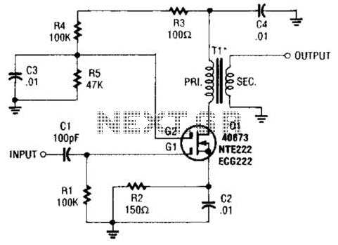
A MOSFET is utilized as a wideband buffer amplifier. T1 is wound on a toroid of approximately specified diameter, using material suitable for the frequency range, typically between 1 MHz and 20 MHz. The turns ratio should be approximately...
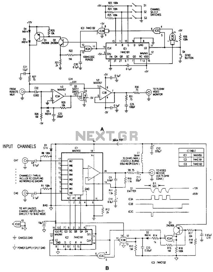
In the video system illustrated in Figures A and R, a single coaxial cable transmits power to a remote location, selects one of eight video channels, and returns the selected signal. This system can choose from several remote surveillance...
A video switcher circuit is required to display multiple sources on a single monitor. The circuit schematic below features the MAX454, which serves as the core component of this video switcher. The MAX454 is a video multiplexer-amplifier manufactured by...