
op amp IR Demodulator Design
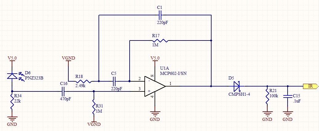
The circuit design for the IR demodulator focuses on detecting the presence of an IR signal modulated at a frequency of 32.678 kHz. The primary components include a series of resistors and capacitors that form a filtering and amplification stage, allowing for effective signal processing. The resistors R1, R2, and R3 are configured to set the gain and input impedance of the circuit, while capacitors C1, C2, and C3 serve to filter high-frequency noise and stabilize the signal.
The voltage sources, V1 and V2, provide the necessary biasing for the circuit, ensuring that the operational amplifier operates within its linear region. The pulse generator simulates the incoming modulated IR signal, which is critical for testing the circuit's response to actual IR signals.
The choice of the LT1722 operational amplifier is significant due to its high speed and low noise characteristics, which are essential for accurately demodulating the IR signal. The calculated gain of approximately 400 indicates that the circuit is designed to amplify weak IR signals to a detectable level. However, to maintain fidelity in the signal processing, the operational amplifier must have a GBWP of at least 14 MHz, which is essential for handling the 32.678 kHz modulation frequency effectively.
In summary, the IR demodulator circuit is designed with specific components and configurations to achieve reliable detection of IR signals. Proper selection of the operational amplifier and careful consideration of circuit parameters are crucial for successful operation. Further testing and refinement may be necessary to ensure the circuit functions as intended, particularly in the context of LTspice simulations and real-world applications.Designing an IR demodulator circuit to replace the one shown in this question. Basically I want to demodulate a simple IR signal modulated at 32. 678 kHz. I just need to know if the signal is present. No packets. Just IR present or not present. I have tried simulating this in LTspice with no success so I am not sure if I`ve done something ver y wrong in spice or in my circuit. I am no pro with LTspice. R1 N001 N006 2. 49K tol=1 pwr=0. 1 R2 Output N003 1Meg R3 N006 N005 1Meg C1 N005 N004 470pF C2 N003 N001 220pF C3 Output N001 220pF V1 N006 0 2. 5 V2 N002 0 5 V3 N004 0 PULSE(0. 05 0 0 0 0. 0000152587890625 0. 000030517578125 200) XU1 N005 N003 N002 0 Output LT1722. tran 12ms. lib LTC. lib. backanno. end The overall gain of the circuit is approximately 400 by my calculations. So, in choosing my op amp I would need a GBWP of 14 MHz or greater Any other critical op amp specifications for this application Note the amp showed is just a place holder until I choose the op amp.
🔗 External reference
Related Circuits
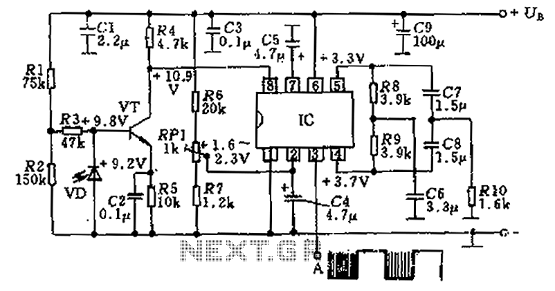
The circuit utilizes an integrated amplifier, resulting in a simple and compact design. The TDA4050 IC is employed, where a weak signal is received by the infrared photodiode (VD) and first passes through a transistor amplifier. The circuit is...

This schematic represents a simple fluorescent lamp driver circuit utilizing two transistors. The circuit employs capacitive ballasting to drive an 8 W standard fluorescent tube efficiently. The two transistors (2SC 1983) and their associated components create an oscillator operating...
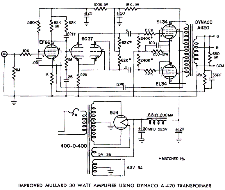
Mullard EL34 push-pull vacuum tube amplifier schematic using Dynaco A420 audio output transformers The Mullard EL34 push-pull vacuum tube amplifier is a classic audio amplification circuit that utilizes EL34 vacuum tubes in a push-pull configuration to deliver high-quality sound reproduction....
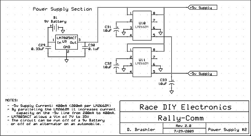
This circuit utilizes the LM2662M integrated circuit from National Semiconductor, which serves as a direct replacement for the MAX1044 but in a smaller surface mount package. Additionally, the main voltage regulator has been upgraded to the LM7805ACT. This circuit...
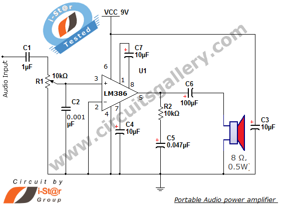
The i-St@r presents a simple mini audio amplifier circuit schematic utilizing the LM386 low voltage audio power amplifier IC. This circuit is designed to power medium-sized speakers from a music player that typically drives only earphones (LM386 headphone). The...
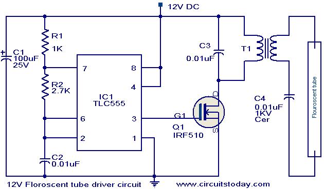
This circuit provides a simple and effective method for driving fluorescent lamps using a 12 V power supply. The circuit consists of an oscillator, a MOSFET switch, and a step-up transformer to power the fluorescent lamp. The TLC 555...