
Opamp Filters schematics
More: First order low or high pass cutoff frequency (-3dB point) = 1/(2pi*R*C)
2nd order low or high pass cutoff frequency (-3dB point) = 1/2pi(R1*R2*C1*C2)^0.5
Example for 200 Hz cutoff frequency - R1=R2=7.95K, C1=C2=0.1uF
The description outlines the application of operational amplifiers (opamps) in the design of active second-order filters, specifically low pass, high pass, and bandpass configurations. Each filter type serves distinct purposes in signal processing by allowing certain frequency ranges to pass while attenuating others.
In the case of the low pass filter, it permits signals with frequencies below the cutoff frequency to pass through while attenuating those above it. Conversely, the high pass filter allows signals above the cutoff frequency to pass, attenuating those below. The bandpass filter combines the characteristics of both, allowing a specific band of frequencies to pass while attenuating frequencies outside this range.
The performance of these filters is characterized by their roll-off rate, which is 12 dB per octave. This means that for every doubling or halving of frequency outside the passband, the output voltage amplitude decreases to one-quarter of its previous value. This property is crucial in applications requiring precise frequency selection or rejection.
The cutoff frequency, or -3 dB point, for first-order filters is calculated using the formula \( f_c = \frac{1}{2\pi RC} \), where R is the resistance and C is the capacitance. For second-order filters, the cutoff frequency is determined by the formula \( f_c = \frac{1}{2\pi\sqrt{R_1 R_2 C_1 C_2}} \).
In the provided example with a desired cutoff frequency of 200 Hz, selecting resistor values \( R_1 \) and \( R_2 \) as 7.95 kΩ and capacitor values \( C_1 \) and \( C_2 \) as 0.1 µF ensures that the filter will effectively operate at the specified frequency. This design methodology is essential for engineers tasked with developing circuits that require specific frequency response characteristics, such as audio processing, communication systems, and signal conditioning applications.The figures below illustrate using opamps as active 2nd order filters. Three 2nd order filters are shown, low pass, high pass, and bandpass. Each of these filters will attenuate frequencies outside their passband at a rate of 12dB per octave or 1/4 the voltage amplitude for each octave of frequency increase or decrease outside the passband. First order low or high pass cutoff frequency (-3dB point) = 1/(2pi*R*C) 2nd order low or high pass cutoff frequency (-3dB point) = 1/2pi(R1*R2*C1*C2)^.5 Example for 200 Hz cutoff frequency - R1=R2=7.95K, C1=C2=0.1uF 🔗 External reference
Related Circuits
Hello everyone, my name is Mike, and I come from a small country called New Zealand. I am currently planning to build a 6L6 push-pull stereo power amplifier and preamplifier. The project involves designing a 6L6 push-pull stereo power amplifier,...
The circuit is designed to be powered directly by a power supply, which is why it does not include a transformer, rectifier, or filter capacitors in the schematic. However, the addition of these components is possible. To operate the...
This chapter contains circuit diagrams for several power supplies designed for pulsed solid-state lasers. These include units suitable for driving the widely used Hughes ruby and YAG rangefinder laser assemblies, one utilizing the flash from a disposable pocket camera,...
Switched-capacitor filters that are preset for a given bandwidth sometimes do not deliver the bandwidth or Q an application requires. By inverting the clock between two switched-capacitor bandpass filters, such as the MSFS1 from Mixed Signal Integration Corp, you...
This chapter contains circuit diagrams for various power supplies designed for pulsed solid-state lasers. These include units suitable for driving the widely used Hughes ruby and YAG rangefinder laser assemblies, as well as one utilizing the flash from a...
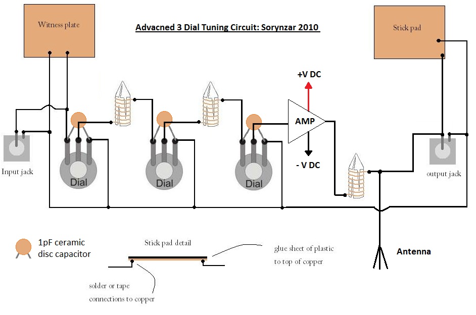
An advanced radionics schematic designed to enhance the power output of a tuning circuit. This schematic outlines a sophisticated approach to improving the efficiency and output power of a tuning circuit used in radionics applications. The circuit typically includes a...